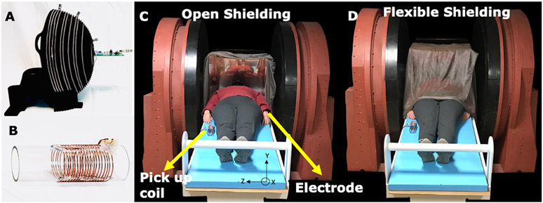
Figure 4: Experimental setup for open 47.5mT scanner.
A) The primary MR coil used for imaging (same spiral design as Fig. 2) tuned to 2.075 MHz with 20 KHz BW. B) EMI detector #1 is a tuned 10 turn RF pick up coil with diameter = 5cm. EMI detector #2 is an ECG electrode (not shown). C-D) The open 47.5mT low field scanner shown with subject and the two EMI detectors, including the electrode attached to subject’s wrist. Experiments were performed in 2 shielding configurations. C) The open shielding configuration included a copper box surrounding the head open on one side. D) The flexible shielding configuration included the addition of copper mesh, grounded to the copper box and draped over the subject.

