
FIGURE 1.
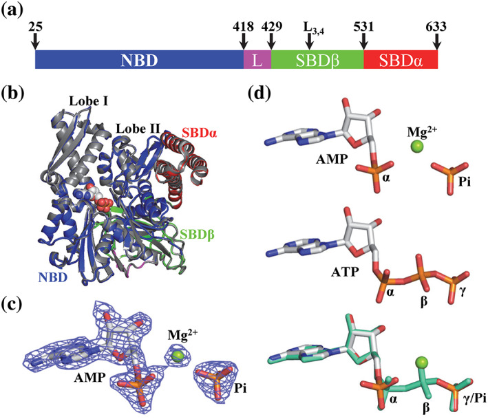
AMP is bound in the nucleotide‐binding pocket of a new Binding immunoglobin protein (BiP) crystal structure, BiP‐AMP. (a) Domain organization of BiP. The residue numbers at the domain boundaries and the L3,4 mutation are labeled on the top. L: the inter‐domain linker. (b) The overall structure of the new BiP‐AMP structure is almost identical to the previously published BiP‐ATP2 structure (PDB: 6ASY). The domain coloring of the BiP‐AMP structure is the same as in (a). The BiP‐ATP2 structure is in gray. The AMP and Pi in the BiP‐AMP structure were shown as spheres. The lobes I and II of the NBD are labeled. (c) The electron density for the bound AMP and Pi in the BiP‐AMP structure is well‐resolved. A 2Fo‐Fc map contoured at 2.0 sigma is shown as blue mesh. The AMP and Pi are shown as sticks and the bound Mg ion as a green ball. (d) Comparison of the AMP‐Pi in the BiP‐AMP structure with the ATP in the BiP‐ATP2 structure. Top: AMP‐Pi; Middle: ATP; bottom: superposition of AMP‐Pi (same color as the top panel) with ATP (green). The AMP‐Pi and ATP are shown as sticks and the bound Mg ion for AMP is highlighted as a green ball. The three phosphates in ATP are labeled as α, β, and γ. The α phosphate and free Pi are labeled as α and Pi, respectively