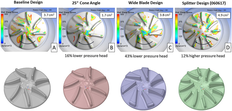
Figure 6.
Contours showing areas of wall shear stress below 500 dyne/cm2 on the right impeller surface for the baseline (A) and three other designs (B, C, D), intended to reduce the fluid volume between the impeller blades. The impeller surface area with wall shear below 500 dyne/cm2, averaged over 360° of rotation, and the change in pressure head vs. the baseline design are provided for each design. The direction of rotation is indicated by the arrows.

