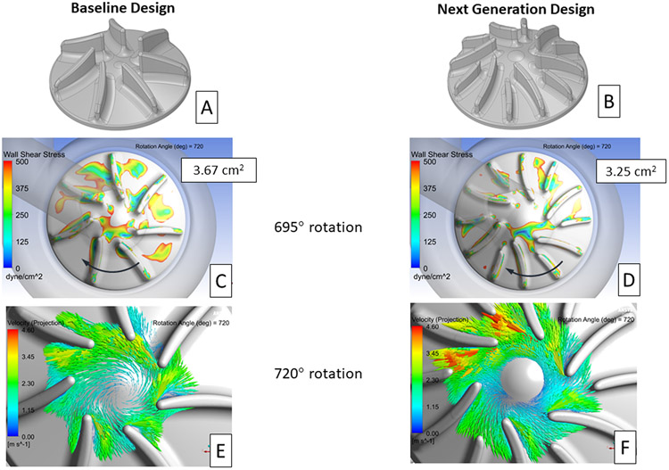
Figure 9.
Isometric images of the baseline (A) and proposed next generation (B) right impeller designs. Contour plots showing areas of wall shear stress below 500 dyne/cm2 on the right impeller surface for the baseline (C) and next generation (D) designs. The impeller surface area with wall shear below 500 dyne/cm2, averaged from 360° to 720°of rotation, is provided in each image. The direction of impeller rotation is indicated by the arrows. In-plane velocity vectors, relative to the rotating frame of reference, for the baseline (E) and next generation (F) right impeller design after 720° of rotation. The plane used in these images is near the mid-level for each right impeller blade.

