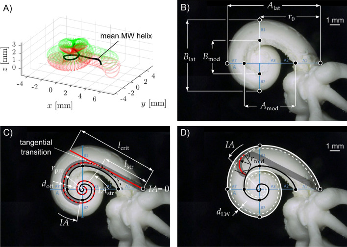
Figure 2.
The methodological approach. (A) The average 3D profile of the cochlear MW extracted from the 15 µCT segmentations described in Ref.37. (B) Base axial view (see methods) at a left cochlea. Depiction of the cochlear dimensions A and B along the cochlear lateral (Alat, Blat) and modiolar wall as well as the distance r0 from the modiolar axis to the center of the round window. Please note that not all segments of the A and B axes are visible in this base axial view - for details see ref.37. (C) visualization of the computed insertion trajectory (in red) based on the individualized MW profile (solid black line) and distance doff between MW and central axis of a perimodiolar array. lstr and IAstr describe the distance and insertion angle respectively after which straight part of the insertion trajectory ends. rpre describes the curvature of the trajectory after the straight section. lcrit represents the distance at which the insertion of a straightened array would touch the lateral wall and potentially cause damage. (D) The computations of the critical radii (rfold) were based on the assumption that if the radius of the precurved implant is small enough for the tip to “stand up” inside the scala tympani, a tip fold-over becomes likely. For this reason, such hypothetical critical radius was computed depending on the different modiolar dimensions and different insertion angles (IAs). The minimal distance between the lateral wall and the central axis of an inserted array was denoted dLW.

