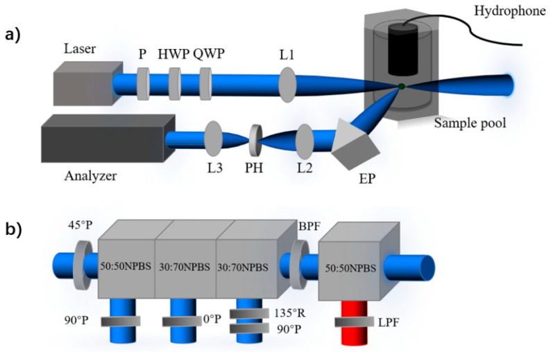
Figure 1.
(a) The schematic diagram of the experiment setup. Linear polarizer (P); half-wave plate (HWP); quarter-wave plate (QWP); convex lenses (L1, L2, and L3); equilateral prism (EP); pinhole (PH). (b) Analyzer of the polarization and fluorescence. Non-polarizing beam splitter cube (NPBS); long-pass filter (LPF); bandpass filter (BPF); quarter-wave plate (R); polarizer (P).

