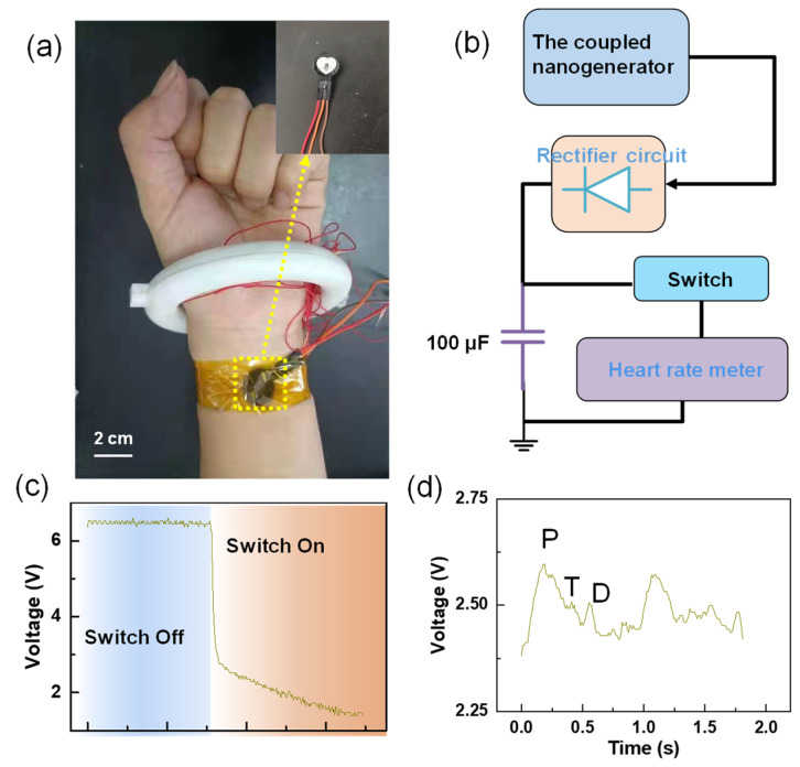
Figure 7.
Self-powered heart rate testing system: (a) the electronic photo of system; (b) the block diagram of system composition; (c) the voltage changed at both ends of the capacitor before and after fast closing. After the switch was closed, the electric quantity in the capacitor began to power the heart rate sensor, and the voltage dropped sharply); and (d) pulse waveform collected.

