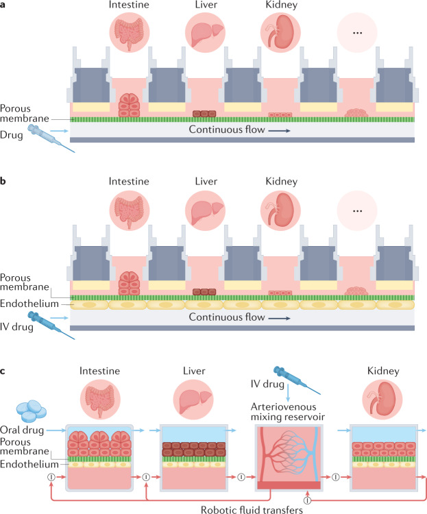
Fig. 2. Schematics showing different multi-organ human body-on-chips formats.
a | A simple fluidic coupling between multiple chambers lined by different organotypic cell types and a common flow chamber in two-chamber organ chip designs; a porous membrane within each chamber separates the overlying cell type from the fluid flow path or transwell inserts containing cells may be placed within open chambers as shown in Fig. 1h. To mimic intravenous (IV) adminstration, the drug can be introduced into the lower flow path. b | A similar multiwell configuration, except that the surface of the shared flow chamber is lined by endothelium. c | A diagram of linked two-channel organ chips containing both parenchymal cells and an endothelium-lined flow channel that are fluidically coupled using a robotic liquid handler to transfer fluids drop-by-drop between the chips and an arteriovenous mixing reservoir. The reservoir is integrated into the system to mimic blood mixing in the central circulation, and it also allows fluid sampling that is more analogous to sampling peripheral blood in a patient. Red arrows indicate the directional fluid flow or transfer path, and the circled ‘I’ depicts points in the circuit where a liquid-handling robot is used to move fluid into or out of the organ models or the arteriovenous reservoir; small blue arrows indicate independent transfers of fluids to and from the parenchymal channels of each chip. In this configuration, IV adminstration is modelled by injecting the drug into the arteriovenous reservoir, whereas oral adminstration is accomplished by introducing the drug into the lumenal channel of an intestine chip. Part c adapted from ref.35, Springer Nature Limited.

