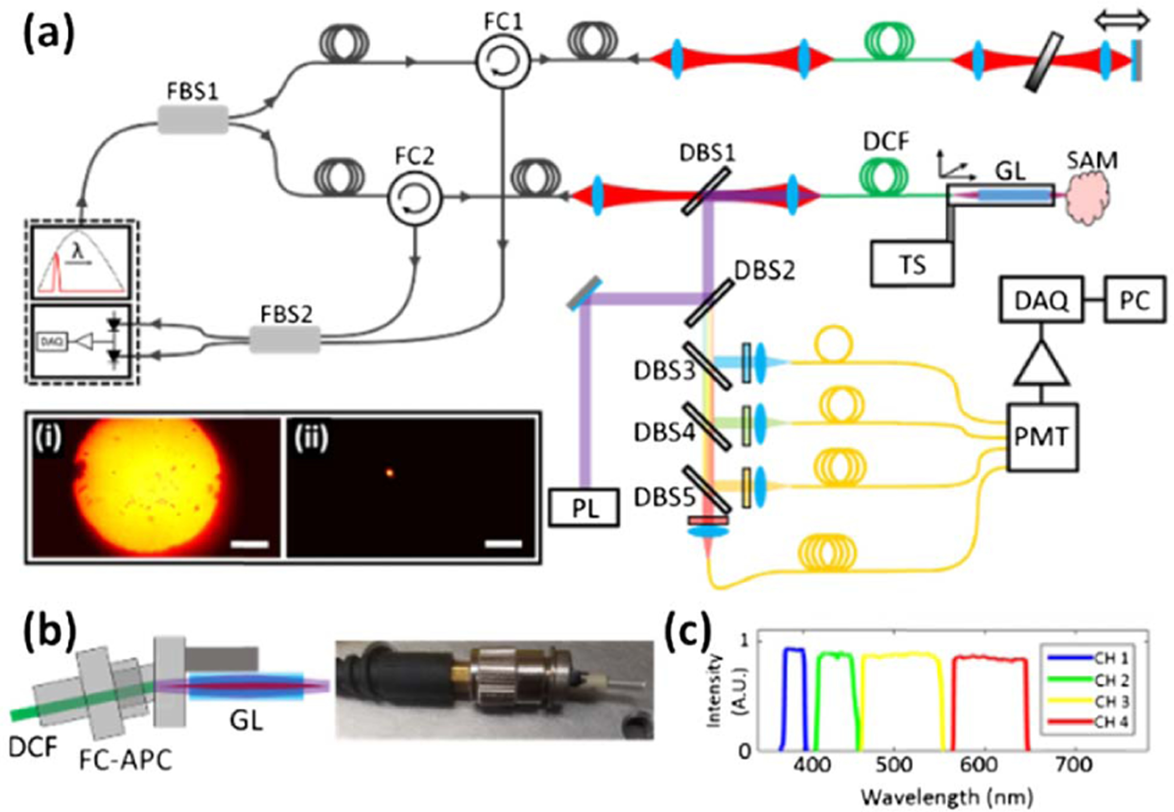
Fig. 1.

(a) Schematic diagram of the simultaneous FLIm and OCT platform. DBS1-DBS5, dichroic beam splitters; DCF, double-clad fiber; DAQ, data acquisition card; FBS1-FBS2, fiber beam splitters; FC1-FC2, fiber circulators; GL, GRIN lens; PL, 355 nm pulsed laser; PMT, photomultiplier tube; TS, translation stage. Inset: image of the DCF distal tip with light propagating in (i) the inner cladding and (ii) the core. Scale bar 100 µm. (b) Schematic (left) and photograph (right) of the DCF probe tip, showing how the connectorized distal end of the DCF interfaces with the GRIN lens. (c) Spectral distribution of the wavelength selection module fluorescence collection bands.
