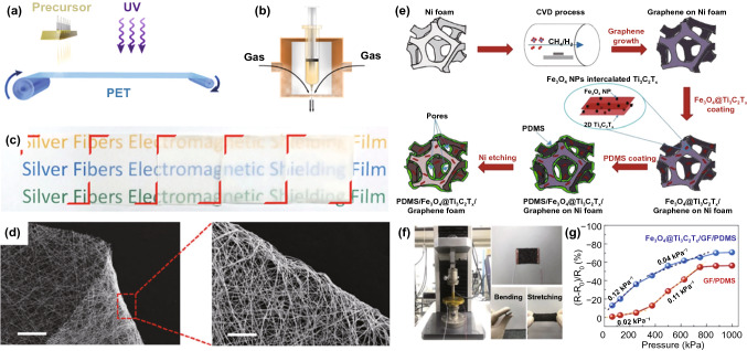
Fig. 15.
a Schematic diagram of the fabrication of AgNF by continuous blow spinning and in situ UV irradiation. b Partially enlarged detail of needle module shows the principle of blow spinning. c A photograph of as-prepared fiber film after different spinning time (from left: 1, 2, 5, 10 and 20 min). d SEM image of a bended AgNF film and its partially enlarged areas, With scale bars of 300 and 50 μm, respectively [143].
Copyright © 2019, Springer Nature. e Schematic diagram of the fabrication procedure for Fe3O4@Ti3C2TX/GF/PDMS composite. f Images of the equipment used for pressure sensing measurement (left), GF-based composite with two electrode lines (right up) and bending/stretching features of GF-based composite (right down). g Plots of relative resistance variation versus applied pressure for GF/PDMS and Fe3O4@Ti3C2TX/GF/PDMS composites [146] Copyright © 2020 Elsevier B.V

