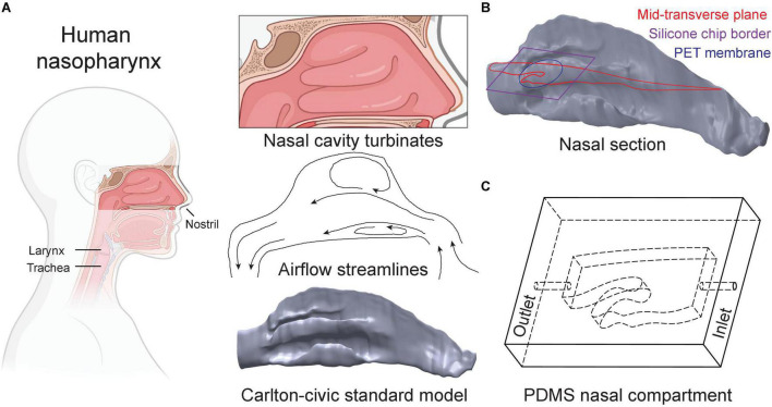
FIGURE 2.
Design of the nasal compartment chip. (A) The nasal cavity features a complex network of turbinate airway passages. The Carlton-Civic Standard Nasal model serves as the basis for our nasal chip design. Nasal flows are dominated by the turbinate structures giving rise to recirculating zones, as illustrated schematically by airflow streamlines in the nasal passages. (B) We recapitulate elements of nasal flow characteristics in a PDMS compartment based on the generic nasal model. A cross-section of the selected geometry is defined parallel to the bulk flow direction (i.e., beginning upwards through the nostril but then curves toward the elongated axis of the trachea) and bound to a maximal size fitting a standard glass microscopy slide (i.e., 40 mm). (C) Schematic drawing depicts the resulting nasal chip compartment, with inner cavities marked by dashed lines and labeled “inlet” and “outlet,” respectively, where holes are punched into the PDMS material to connect tubing (see text for details).

