. 2022 Mar 10;22(7):1286–1296. doi: 10.1039/d1lc00878a

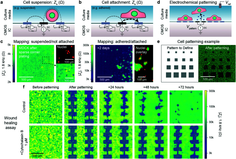
Fig. 2. Electrically mapping and patterning cells using a CMOS electrode array for real time attachment and kinetics measurements. a and b, Cell attachment measurement schematics of a suspended/not attached cell (a) and adhered/attached cell (b). An AC voltage is applied to an electrode (n) with the remainder of the electrodes' (1, …, n − 1, n, n + 1, … 4096) currents measured via transimpedance amplifiers. The presence of a cell affects the field distribution in solution: an unattached cell blocks field lines decreasing cross-electrode coupling while an attached cell spanning two electrodes increases their coupling. To generate a cell map, the applied signal is scanned across the array (40 s per scan) and the cell-substrate impedance, Zs, is calculated (ESI Discussion 1). c, The attachment of MDCK cells after a sparse corner plating was recorded via a Zs measurement every 7.5 min, see Video S1 for a full time course. d, Cells can be selectively removed from electrodes using electrochemically generated gas. A voltage, Vpattern, biased negative to produce H2 gas is commonly used (≤1.0 V versus Ag/AgCl). e, Various sized squares (left) were used for patterning MDCK cells and confirmed via a nuclei fluorescence image (right); a co-culture was further defined via a second plating, Fig. S4b. f. Both mapping and patterning techniques were combined to form a wound healing kinetics assay. The healing was electrically mapped via Zs measurement once a day for a control (top) and drug (cytochalasin B) application (bottom); see Video S2 for a real-time regrowth example. Full healing was observed after 72 hours for the control while the culture treated with cytochalasin B showed almost no cell migration or growth.

Fig. 2