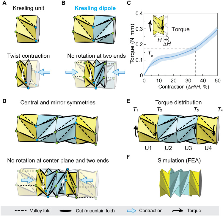
Fig. 1. Mechanism of the four-unit Kresling crawler based on the Kresling dipole.
(A) Schematic of a Kresling unit, showing contraction coupled with a twist deformation. (B) Schematic of a Kresling dipole made of two standard Kresling units with reverse crease directions, showing no rotation at the two ends (green circles) but rotation at the center plane (blue circles) during contraction. (C) The experimentally measured torque contraction curve of the Kresling unit. Contraction is defined as ∆H/H, where H is the initial height of the unit and ∆H is the difference between the initial and contracted heights. Parameter Te is defined as the corresponding torque at 35% contraction of the unit for effective crawling motion. The solid line is the averaged responses of three Kresling unit samples, and the shaded region represents the range of responses. (D) Schematic of the Kresling crawler made of two Kresling dipoles, showing no rotation at the center plane and two ends. (E) The required torque distribution to actuate the Kresling crawler for simultaneous contraction of all units. (F) FEA verification of the derived torque distribution for simultaneous contraction of all units.

