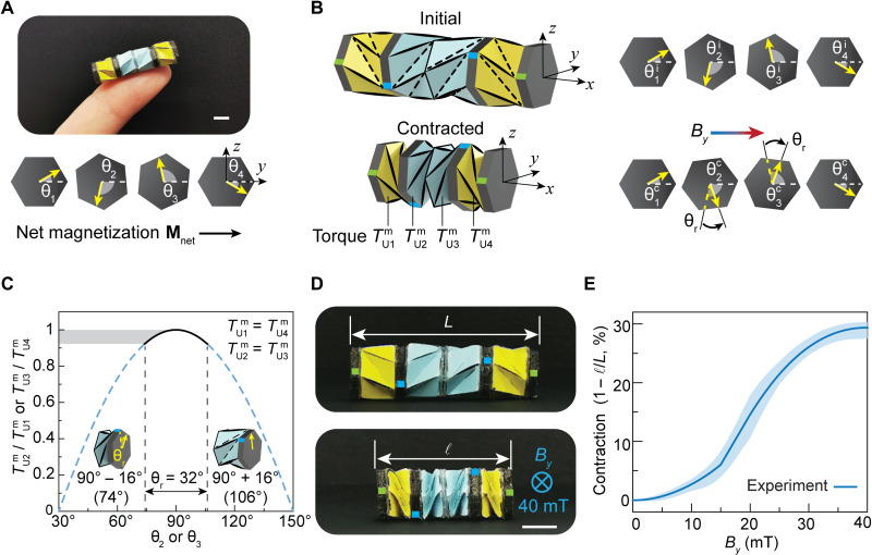
Fig. 2. Magnetic actuation mechanism of the Kresling crawler.
(A) Image of a fingertip holding the fabricated Kresling crawler and designed magnetization directions of attached four magnetic plates for distributed torques. (B) Crawler configurations and magnetization directions at the initial state and the contracted state. By is the magnetic field applied to the crawler along its net magnetization direction. Angle θr is the total rotation angle of θ2 or θ3 during contraction. , , , and are torque magnitudes on units U1, U2, U3, and U4 under magnetic actuation, respectively. Green marks on the vertices of the magnetic plates indicate no rotation at the two ends of the Kresling crawler. (C) Torque ratio between units U1 and U2 (U4 and U3) during contraction. Contraction of the unit of 35% (rotation angle θr of 32°) is defined as an effective crawling motion under a reasonably small torque. Note that angles θ1 and θ4 stay unchanged during contraction. Angles θ2 and θ3 are designed to swing between 106° and 74° to minimize the dynamic fluctuation of magnetic torques during contraction. (D) The magnetically actuated contraction under a magnetic field of 40 mT. (E) Characterization of the Kresling crawler contraction at different magnetic field magnitudes. Contraction is defined as 1 − ℓ/L, where L and ℓ are lengths of the crawler at the initial state and after contraction, respectively. The solid line is the averaged responses of three Kresling crawler samples, and the shaded region represents the range of responses. Scale bars, 5 mm.

