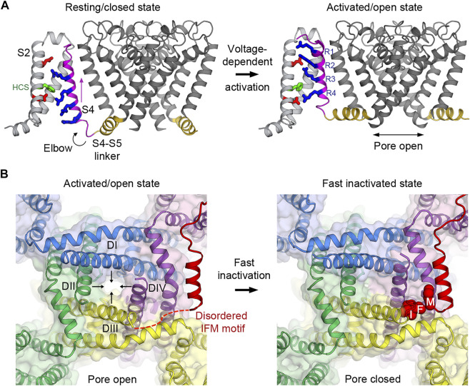
FIGURE 2.
Voltage-dependent activation and inactivation of NaV channels. (A) Structural transition of the voltage sensor and the pore during the voltage-dependent activation from resting/closed to activated/open states in the bacterial NaVAb channel. Four gating charge arginines (R1–R4) are shown in blue. Extracellular and intracellular negative clusters are shown in red. Phenylalanine in the hydrophobic constriction site (HCS) is shown in green. S4 (magenta) moves outward, passing two gating charges through the HCS. The S4–S5 linker (gold) connects the S4 movement to gating of the pore. (B) Structural transition of the activation gate during the voltage-dependent inactivation from activated/open to fast inactivated/closed states in rat NaV1.5. Arrows indicate the directions of movement of the S6 segments. The IFM motif latches onto its receptor site formed by the S4-S5 linker and S6 of DIII and DIV to inactivate the channel and close the pore.

