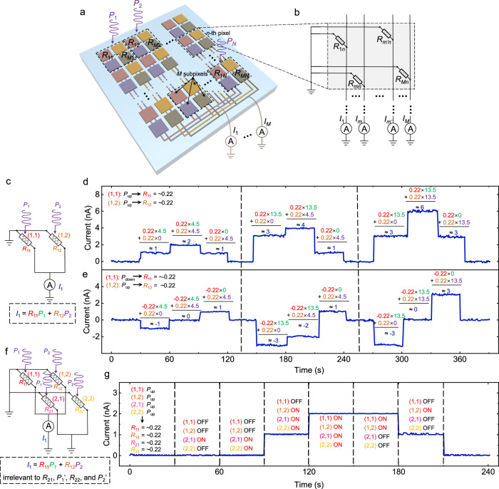
Fig. 4. In-sensor MAC operations in FE-PS-NET.
a Schematic illustration of the architecture of the FE-PS-NET. b Schematic circuit diagram for a pixel in the FE-PS-NET. c Schematic circuit diagram for a 1 × 2 FE-PS-NET. d, e Time-resolved currents (I1) measured during the applications of different illuminations to the (1, 1) and (1, 2) FE-PSs. In d the (1, 1) and (1, 2) FE-PSs are both set in the complete Pup state, while in e the two devices are set in the complete Pdown and Pup states, respectively. In each period during which at least one FE-PS is illuminated, the MAC operation is directly expressed as the equation containing the experimental values of photoresponsivity, optical power, and output current. Their corresponding units are mA/W, μW, and nA, respectively (not shown). f Schematic circuit diagram for a 2 × 2 FE-PS-NET. g Time-resolved currents (I1) measured during the applications of different illuminations to the (1, 1), (1, 2), (2, 1), and (2, 2) FE-PSs. All the FE-PSs are set in the complete Pup state, and the illumination sequences are indicated in the corresponding periods while the optical power for illumination (~4.5 μW) is not shown.

