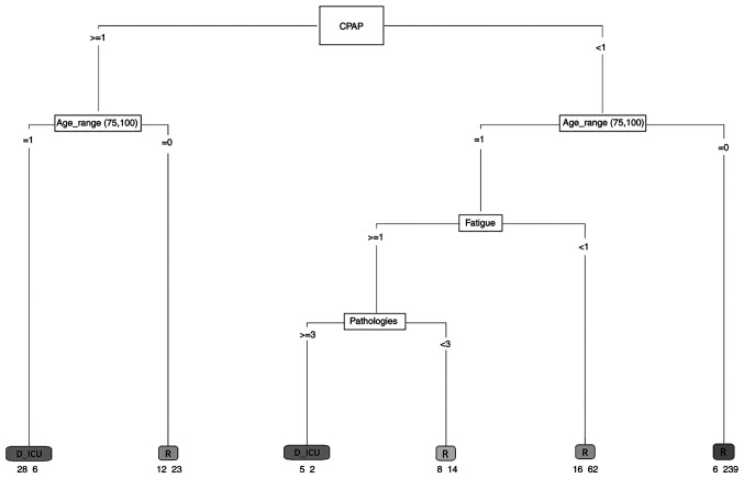
Figure 3.
Decision tree algorithm. The decision tree contains a root node, internal nodes and leaf or terminal nodes. Each leaf is assigned for a class label. The numbers under the leaves represent the output result. For example, D_ICU 28-6 indicates that there were 34 subjects in this class: 28 individuals who died or were transferred to the ICU and 6 individuals who recovered. CPAP, continuous positive airway pressure; R, recovered; D_ICU, died or were transferred to the intensive care unit.

