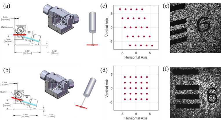
Fig. 2.
CAD drawing of GVS012 scanning galvanometer pair (courtesy of Thorlabs, Inc.) and schematic of resonant galvanometer with outgoing beam scan direction and angle from resonant galvanometer shown as a red line for comparison against the tilt angle of first galvanometer mirror shown in blue for (a) resonant galvanometer alignment with axis of rotation perpendicular to breadboard and (b) resonant galvanometer alignment with 15° tilt to align axis of rotation perpendicular to that of first galvanometer mirror. Resulting scans at the imaging plane for each configuration are shown as the output of a Zemax model for scan angles between −10 and 10 degrees in (c) and (d), and with sample images of a fluorescent USAF target in (e) and (f), for configurations (a) and (b) respectively.

