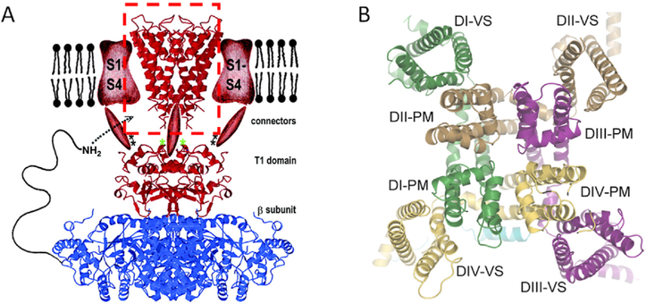
Fig. 4.
Structures of the voltage-gated channel family. A. An early mockup cartoon representing a hypothetical KV channel in side view. The 2000 cartoon is a composite of several structures filled in with some artistic sketching. At the top center in a red dashed box is the crystal structure of the original KcsA channel (red), shown as a ribbon diagram of the inverted teepee. On either side, in the membrane, are sketched the expected positions of red voltage sensor domains (S1-S4). Below the membrane are sketched red cytoplasmic connectors joining to another crystal structure showing a cytoplasmic tetramerization domain (T1) of KV1.1 (red) complexed with a KV channel β2 subunit (blue), again as ribbon structures (Gulbis et al., 2000). This composite, anticipates the finding that channels may have extensive extracellular and intracellular components that make them much more than a simple conducting donut. B. A 2021 cryo-EM structure of NaV1.5 in face view from the cytoplasmic side. The pseudotetramer is formed from a single principal subunit with four repeat domains (DI-DIV) as in Fig. 2A. Each repeat has a different color. Around the outside are the four voltage-sensor domains (VS), and forming the pore in the middle are the four pore modules (PM). To obtain this structure, an intracellular component of the inactivation process was mutated to keep the channel open. After (Jiang et al., 2021).

