. 2022 Mar 17;10(14):7626–7636. doi: 10.1039/d2ta00876a

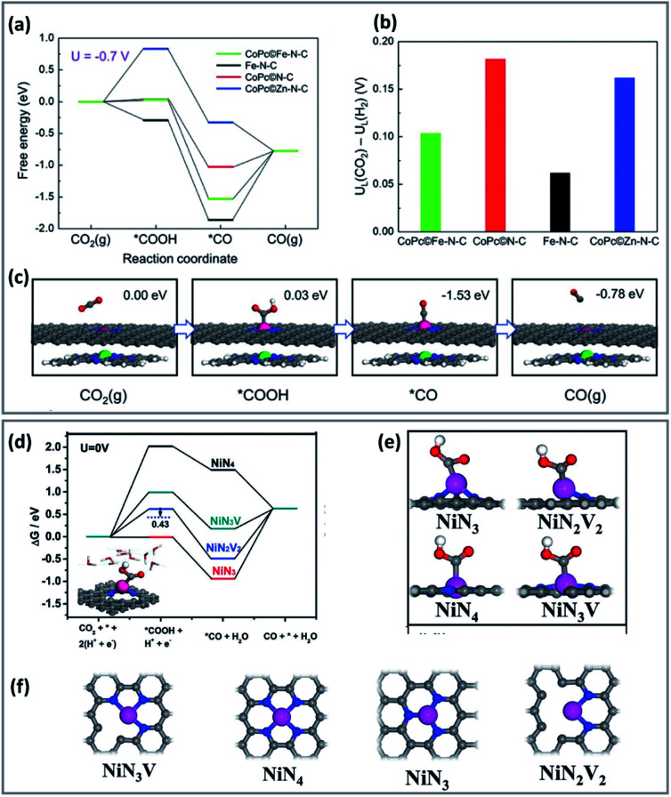
Fig. 1. Computational results of CO2RR process on different catalysts. (a) Free energy diagram for the CO2RR to CO at U = −0.7 V vs. RHE on the Fe site in CoP/Fe–N–C, Fe site in Fe–N–C, Co site in CoP/N–C, and Zn site in CoP/Zn–N–C, respectively. (b) The differences in limiting potentials for CO2RR (UL (CO2)) and HER (UL (H2)) on the active sites. (c) Schematic atomic structure of CO2RR process on the Fe site in CoPc/Fe–N–C with the free energies at U = −0.7 V versus RHE. DFT calculations (copyright 2019 Wiley-VCH).65 (d) Free energy diagrams solvation effect corrections for the CO2RR and the HER. (e and f) Optimized atomic structures of different Ni–N structures with Ni atoms coordinated with 4 N atoms (NiN4), 3 N atoms (NiN3 and NiN3V), 2 N atoms (NiN2V2) (copyright 2012 Science).67.

Fig. 1