
Figure 1.
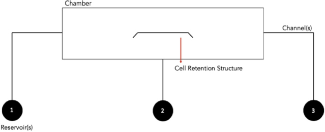
Design layout of the microfluidic chip. A structure of the chip, with the left (1) and right (3) reservoirs serving as the cell inlet and waste reservoirs, respectively, whereas the middle reservoir (2) is used for reagent delivery
Official websites use .gov
A
.gov website belongs to an official
government organization in the United States.
Secure .gov websites use HTTPS
A lock (
) or https:// means you've safely
connected to the .gov website. Share sensitive
information only on official, secure websites.
Design layout of the microfluidic chip. A structure of the chip, with the left (1) and right (3) reservoirs serving as the cell inlet and waste reservoirs, respectively, whereas the middle reservoir (2) is used for reagent delivery