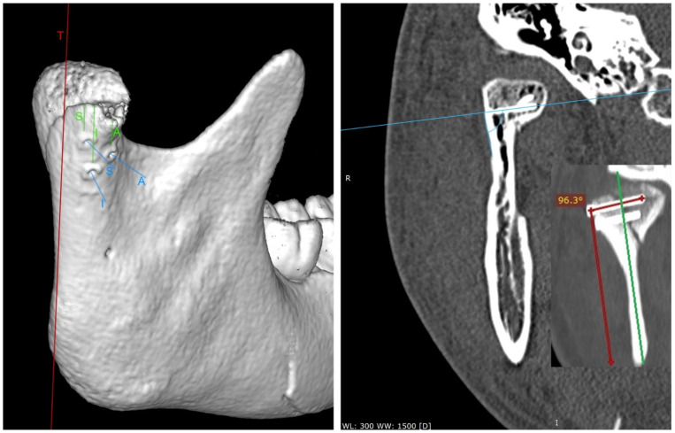
Figure 4.
Postoperative radiological examination. On the left, computed tomography acquired immediately after the surgery (view ¾ laterally). This 3D imaging reconstruction shows the screw location used in the study. T—tangent line in the lateral view to the posterior edge of the mandible. The measurements of the distance between the screws and the fracture line are marked in green. The screw insertion directions are shown in blue. S—superior screw; I—inferior screw; A—anterior screw. On the right, a coronary cross-section (taken 12 months after the end of treatment) set on sample screws and measures their angle of insertion into the bone.

