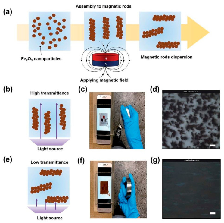
Figure 16.
Schematic illustration of the formation of the magnetic microrods by applying a magnetic field (a). Schematic illustration of magnetic rods vertically oriented by controlling the magnetic field (b). Smart phone screen showing the university logo through the transparent cavity filled with magnetic rods (c). Microscopic image of the vertically oriented magnetic rods (d). Schematic illustration of magnetic rods oriented parallel to the surface by controlling the magnetic field (e). Smart phone screen showing the university logo through the transparent cavity filled with magnetic rods when the rods are in parallel to the surface (f). Microscopic image of the parallel oriented magnetic rods (g). The scale bars represent 100 μm (adapted from [112] with permission from the Royal Society of Chemistry).

