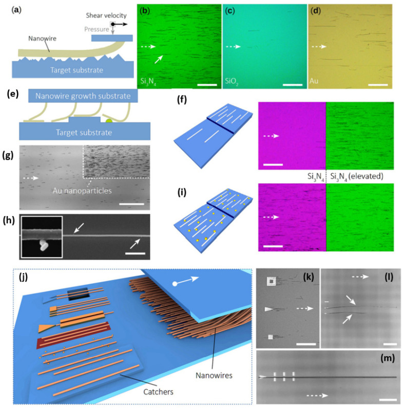
Figure 14.
(a–d) Friction-based SCCP concept. (a) Schematic illustration of a nanowire in mechanical contact with a surface. The frictional force is predominantly influenced by the shear velocity vector, applied load, contact morphology, and materials of the nanowire and the target substrate. (b–d) Optical microscopy images of nanowires transferred in a lubricant-free manner (exemplified by the solid arrow in (a)) onto Si3N4, SiO2, and Au surfaces. The dashed arrow represents the shear direction of the growth substrate. (e–i) Influence of local surface features on SCCP. (e) Schematic illustration showing the interaction of a nanowire with a previously deposited nanowire (left), the interactions of nanowires with a step (center), and the interaction of a nanowire with a nanoparticle (right). (f) Schematic and optical images of an 80 nm step in Si3N4, revealing that nanowires are preferentially deposited onto the elevated area. (g) Optical micrograph depicting an area decorated locally with Au nanoparticles of 50 nm in diameter. The nanoparticles increase the frictional force acting on the nanowires and, therefore, significantly increase the deposited nanowire density. (h) SEM image of a nanowire on a surface decorated with Au nanoparticles of 20 nm in diameter. The arrows indicate the positions of nanoparticles. The inset shows a magnified region containing a nanowire and Au nanoparticles. (i) The effect of the step, as shown in (f), is masked when Au nanoparticles (here, 50 nm in diameter) are present. The shear direction of the growth substrate is indicated in all images by a dashed arrow. The scale bars for (f–i) represent 100 μm, and that for (h) represents 1 μm. (j–m) Towards SCCP nano-device fabrication. (j) Schematic illustration of various catcher concepts, listed from front to back: elevated plateaux, nanoparticles, changes in surface roughness or material composition, catchers with selectivity or guiding rails, catchers for single and multiple-nanowire positioning, and catchers fabricated out of the substrate material with nanowires spanning a trench. (k) Catchers on SiO2 of different lateral shapes, leading to an increased nanowire density adjacent to the catcher. The dashed arrow indicates the shear direction of the nanowire growth substrate. (l) Gold catchers on Si3N4 with the ability to position single nanowires (see white arrows). The width of a single structure is 300 nm. (m) Optical image of one triangular and six rectangular Au structures for single-nanowire positioning. When the triangular structure catches a single nanowire, the rectangular structures appear to assist, serving a function similar to that of a guiding rail, as revealed by experiments. Reproduced from [143].

