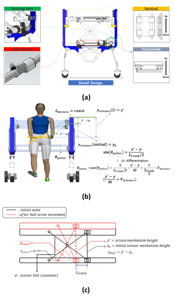
Figure 7.
(a) The detailed design of the scissor mechanism. The driving part (green and red parts in (a) consists of the BLDC motor and ball screw. If the BLDC motor rotates, the ball screw changes the motor rotation to linear motion. Then, the bottom of the scissor mechanism moves in the horizontal direction through the LM guide (gray part in (a), and the top of the scissor mechanism moves in the vertical direction through the LM guide (yellow part in (a). As a result, this vertical movement facilitates the BWS of the patient and pelvic obliquity movement along the frontal plane. (b,c) The kinematic model. (b) The modeling of the ball screw to the scissor mechanism. (c) The scissor mechanism for the human pelvic obliquity movement.

