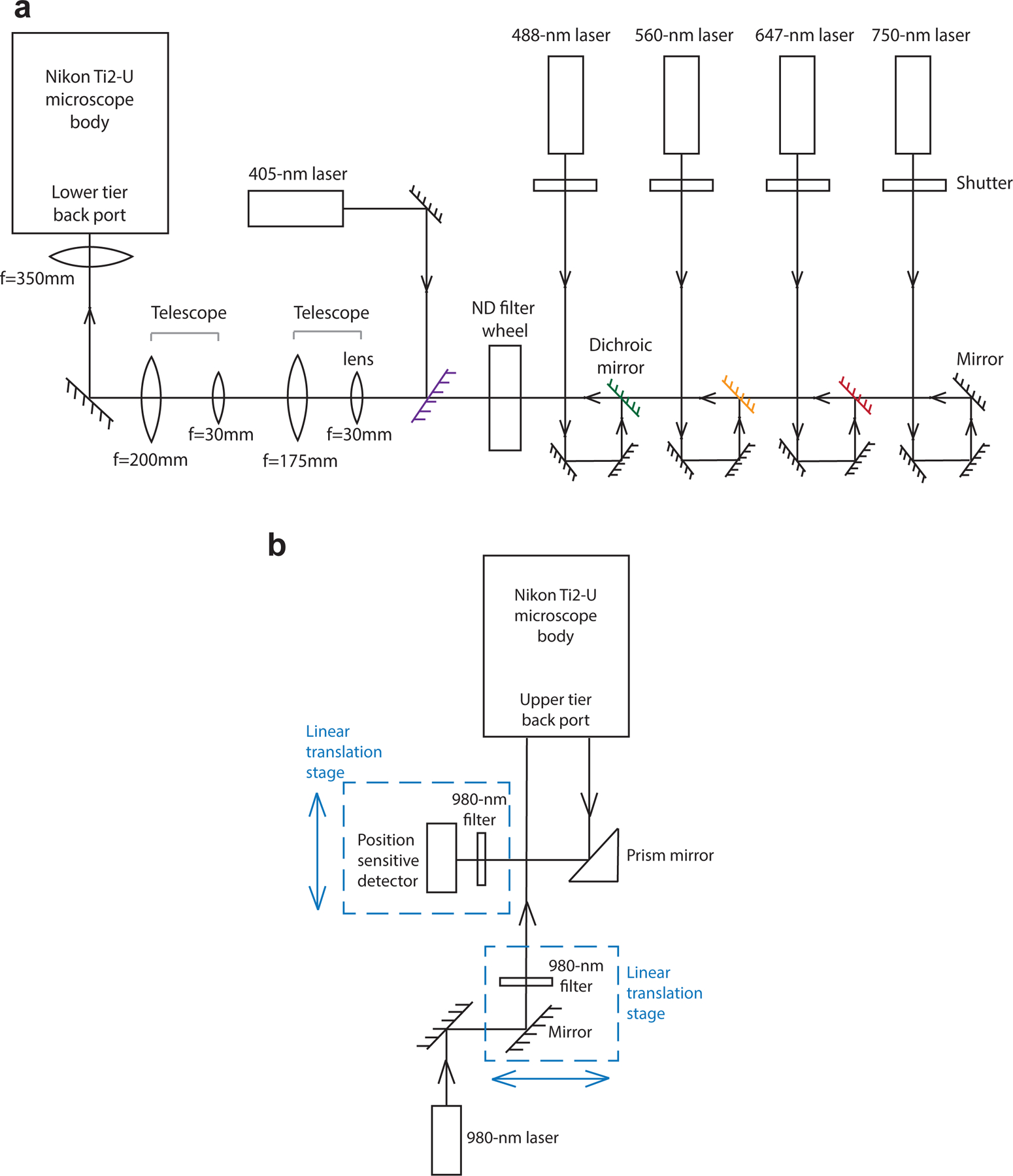
Fig.6. Schematic illustration of the home-built microscope and focus-lock system.

a, A schematic illustration of the home-built microscope setup. The 750-nm, 647-nm, 560-nm and 488-nm lasers are firstly directed through a neutral density (ND) filter wheel, which tunes laser intensities. The digitally controlled 405-nm laser and the four laser lines above are combined, pass through two telescopes for beam diameter expansion, and are directed into the lower tier back port of the Nikon Ti2-U microscope body. b, A schematic illustration of the home-built focus-lock system. A 980-nm laser passes through a 980-nm bandpass filter and is aligned to be parallel with the optical axis of the objective lens but translated away from the center axis. The back reflected 980-nm laser displaced to the other side of the center axis is captured by a prism mirror and is directed to a position sensitive detector.
