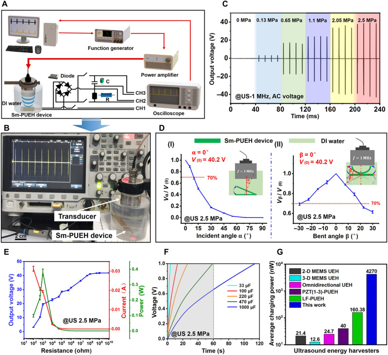
Fig. 2. Electrical output characteristics of Sm-PUEH device.
(A) Schematic diagram of electrical output test system for the Sm-PUEH device. (B) Sm-PUEH device in the test. (C) The output voltage signal of Sm-PUEH device measured under 1-MHz US with different intensities. (D) The output voltage signal of Sm-PUEH device at different US incident angles (I) and at different bending angles (II). (E) The output voltage, current, and power of Sm-PUEH device under different load conditions driven by a pulse US with 2.5 MPa. (F) Charging curves of various capacitors (33, 100, 220, 470, and 1000 μF) with Sm-PUEH device driven by a pulse US with 2.5 MPa. (G) Comparison of average charging power with different US energy harvesters. 2-D, two-dimensional; MEMS, Micro-Electro-Mechanical System.

