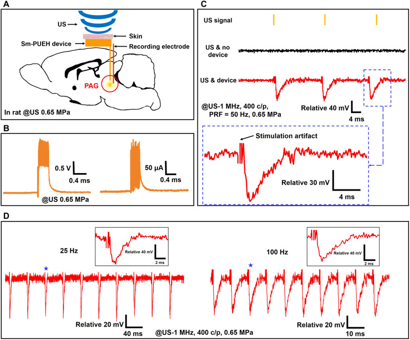
Fig. 4. The PAG activation by Sm-PUEH device.
(A) Schematic diagram of in vivo experimental design of DBS using Sm-PUEH device implanted in rats, where the stimulation electrode is placed in the PAG brain area (7 mm posterior to the bregma, 0.5 mm lateral to the midline, 5.5 mm deep), and the recording electrode is near the stimulation electrode. (B) Voltage and current measurement in the brain tissue. (C) In vivo recorded local field potential (LFP) signal (stimulus artifacts cropped for clarity) under a 1-MHz US (US-400 c/p, PRF = 50 Hz, 0.65 MPa) without implanted device (US & no device), and with implanted device (US & device). (D) In vivo recorded PAG activities by Sm-PUEH device stimulation with PRF of 25 Hz (left) and 100 Hz (right) (stimulus artifacts cropped for clarity). Insets (indicated by stars) show the zoom-in of individual LFP.

