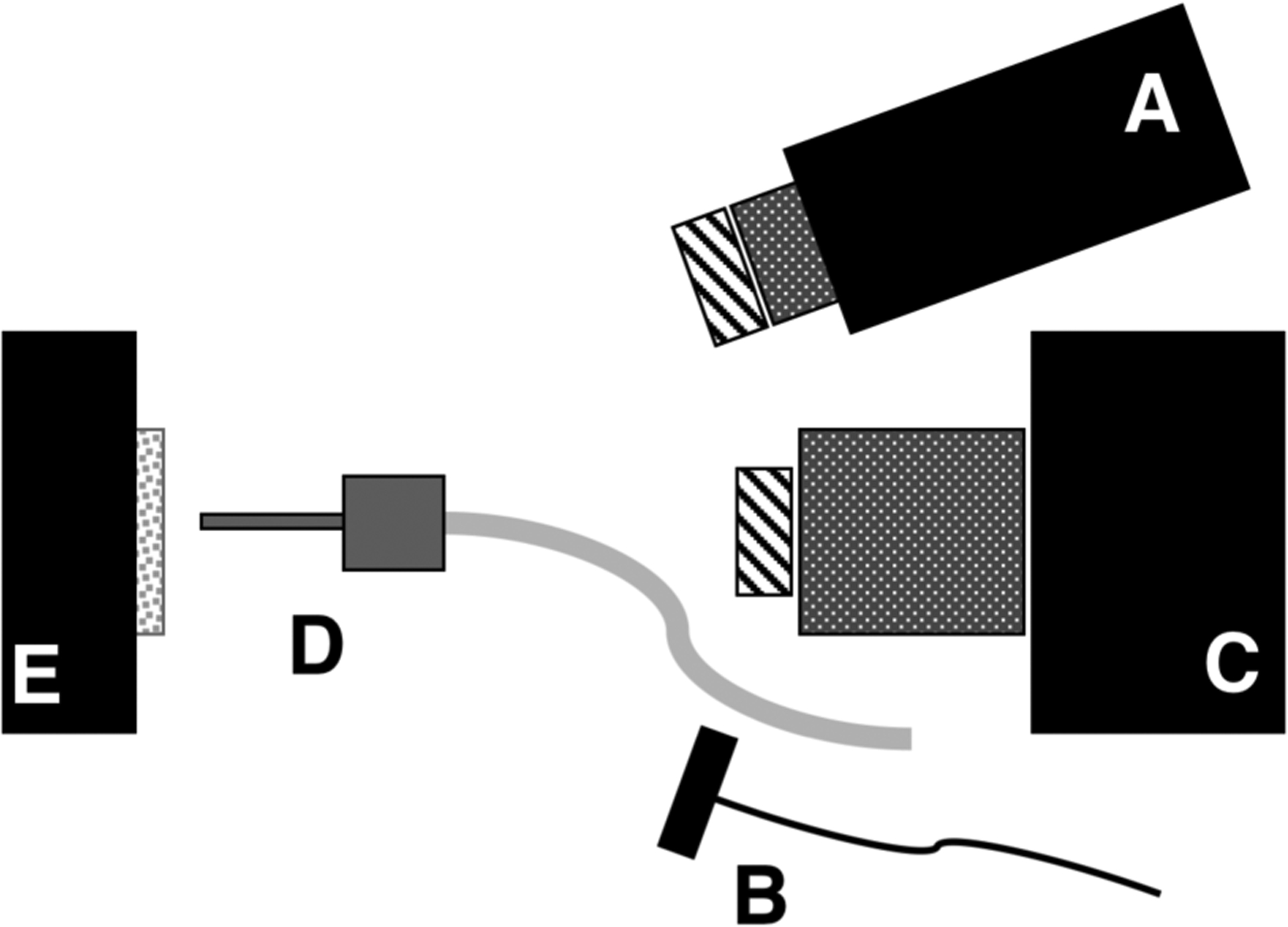
Fig. 1.

Schematic of the experimental setup showing (A) tungsten-halogen light source with bandpass filters, collimating lens and polarizer, (B) polarized 1950 nm fiber optic light source, (C) Xenics extended range InGaAs camera with lens and polarizer, (D) air nozzle and (E) tooth samples mounted on XYZ stage. Light sources A & B were positioned on the same side for these measurements.
