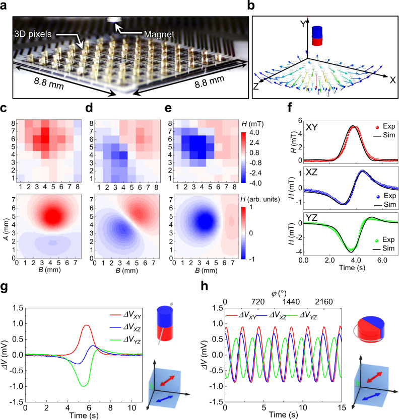
Fig. 3. Static mapping and dynamic tracking of magnetic objects.
a Image of an IMOS device together with a small NdFeB permanent magnet. b Simulation result of the magnetic vectors at the locations of the 8 × 8 sensor pixels. c–e Static mapping of the strengths of the magnetic stray field by SXY, SXZ and SYZ sensor arrays on the XY, XZ and YZ planes, respectively. The top panel is from the experimental results and the bottom panel is from simulation. The magnet and its relative position to the sensor array is shown in a. f Simulation result of the dynamic responses of SXY, SXZ and SYZ in a single pixel to the linear motion of a magnet. The dotted lines are measured results and the continuous lines are from simulation. g Dynamic voltage response to a linear motion of the NdFeB permanent magnet monitored by a single pixel. h Dynamic tracking of the rotation of a NdFeB permanent magnet by a single pixel. The output voltages for SXY, SXZ and SYZ change periodically with constant magnitudes emphasizing the stability of the sensors. The 90° phase shift between the signals from SXY and SYZ indicates the orthogonal folding of these two sensing planes. The relative positions of the magnets to the sensor pixels as well as the magnetization directions of the magnets are schematically illustrated on the right of the response curves. Source data are provided as a Source Data file.

