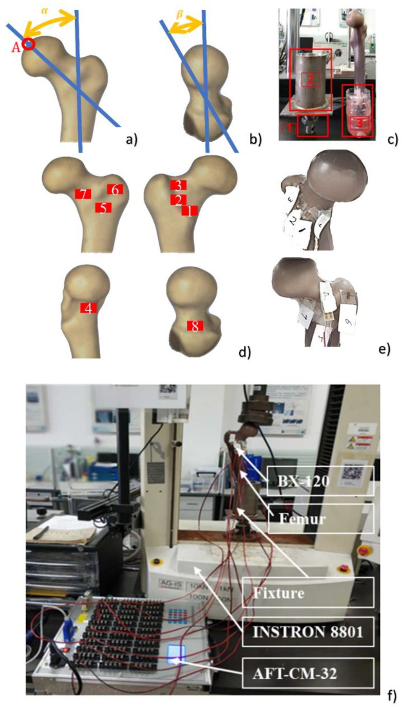
Figure 1.
The experimental layout of mechanical tests: (a) angle α (0–135°) with reference to the long axis of the femur in the frontal plane; (b) angle β (0–45°) with reference to the femoral neck axis in the horizontal plane; (c) fixation method and device of the composite femur; (d) position of strain gages on the femur in the numerical simulation; (e) position of strain gages on the femur in mechanical tests; (f) the experimental device of composite femur compression. Point A was the central position of the spherical region surface with a 35 mm diameter on the femoral head.

