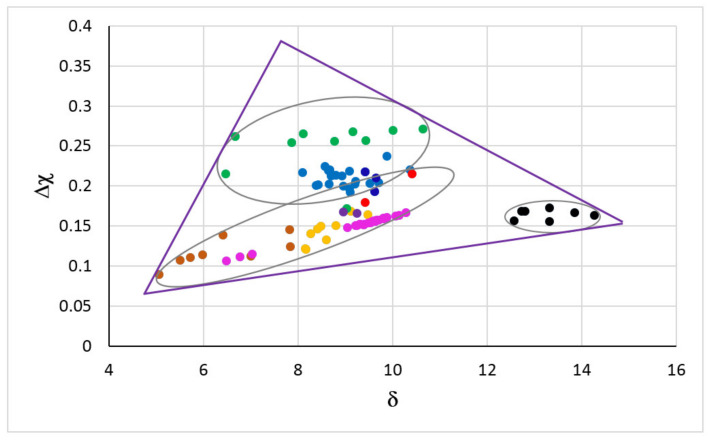
Figure 1.
Δχ versus δ map of RM(Nb)ICs, RM(Nb)ICs/RCCAs, RM(Nb)ICs/RHEAs and RHEAs or RCCAs with addition of Nb and Si. RM(Nb)ICs: Orange circles for alloys of B-free Nb-SM-Met-TM-RM systems with Nbss and Nb5Si3 with/without Laves phase; blue circles for alloys of B-free Nb-Si-TM-RM systems with Nbss and Nb5Si3; black circles for alloys of Nb-SM-B-TM-RM systems with Nbss and 5-3 silicide alloyed with boron [7]. SM = simple metal and Met = metalloid element (Al, B, Ge, Si, Sn). TM = transition metal (Cr, Hf, Ti); RM=Mo, Ta, W. RHEAs and RCCAs; green circles for alloys with bcc solid solution plus M5Si3 silicide(s) [2]; red circles for alloys with bcc solid solution plus M5Si3 silicide(s) and Laves phase(s) [2]; darker orange circles for alloys with bcc solid solution plus Laves phase without M5Si3 silicide [17] (M = TM, RM). RM(Nb)ICs/RCCAs; purple circles for the alloys OHS1 [18] and ZF9 [19] with Nbss and Nb5Si3; dark blue circles for the alloys JZ3+, JZ4 and JZ5 with Nbss and Nb5Si3 [20,21]. RM(Nb)ICs/RHEAs; pink circles for the alloys MG5, MG6 and MG7 with Nbss and Nb5Si3 and other intermetallics [11,22]. For triangle see text. For the nominal compositions of the alloys see the Appendix A.

