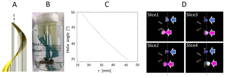
Figure 2.
(A). Helicoidal holder for the fiber bundle; (B). Picture of the object; (C). Variation of helix angle in function of the distance, r, to the z axis which intersect the center of the support; (D). Ground truth MR images of the phantom (four axial slices from top to bottom, approximate slice locations are indicated in (B)), shown as color-coded FA maps, where the pink and blue arrows indicate the straight and helical bundles, respectively.

