

Abstract
In-vivo optic nerve head (ONH) biomechanics characterization is emerging as a promising way to study eye physiology and pathology. We propose a high-accuracy and high-efficiency digital volume correlation (DVC) method to characterize the in-vivo ONH deformation from optical coherence tomography (OCT) volumes. Using a combination of synthetic tests and analysis of OCTs from monkey ONHs subjected to acutely elevated intraocular pressure, we demonstrate that our proposed methodology overcame several challenges for conventional DVC methods: First, a pre-registration technique was used to remove large ONH rigid body motion in OCT volumes which could lead to analysis failure; second, a modified 3D inverse-compositional Gaussian Newton method was used to ensure sub-voxel accuracy of displacement calculations despite high noise and low image contrast of some OCT volumes; third, a tricubic B-spline interpolation method was applied to improve computational efficiency; fourth, a confidence parameter was introduced to guide the searching path in the displacement calculation; fifth, a confidence-weighted strain calculation method was applied to further improve the accuracy. The proposed DVC method had displacement errors smaller than 0.037 and 0.028 voxels with Gaussian and speckle noises, respectively. The strain errors in the three directions were less than 0.0045 and 0.0018 with Gaussian and speckle noises, respectively. Compared with the conventional DVC method, the proposed method reduced the errors of displacement and strain calculations by up to 70% under large body motions, with 75% lower computation time, while saving about 30% memory. Our study demonstrates the potential of the proposed technique to investigate ONH biomechanics.
Keywords: Digital volume correlation, Optic nerve head, Optical coherence tomography, Deformation characterization, Rigid body motion
1. Introduction
The biomechanics of the optic nerve head (ONH) in the posterior pole of the eye play a central role in several pathologies, and are therefore important to prevent blindness [1, 2]. In glaucoma, for instance, increases in intraocular pressure (IOP) have been causally associated with higher risk of neural tissue damage and the consequent vision loss [3, 4]. The mechanisms by which higher IOP contributes to the neuropathy are not fully understood, but are known to involve IOP-induced deformations of the retinal ganglion cell axons as they pass through the ONH [5]. Improved diagnosis and treatment of glaucoma, and of other biomechanics-related ocular pathologies, therefore requires an accurate and efficient method to measure ONH biomechanics in vivo [6, 7].
Optical coherence tomography (OCT) has emerged over the last decade as the most widely used tool to image the ONH in vivo [8–17]. OCT allows acquiring three-dimensional (3D) volumes of the ONH with μm-scale resolution, and with sufficient signal penetration to visualize the lamina cribrosa region within the ONH. The lamina cribrosa is where glaucomatous neural tissue degeneration starts and is therefore of crucial interest in early diagnosis and treatment of this pathology [5, 18, 19].
Also substantially advanced over the last couple of decades is the image analysis technique of digital volume correlation (DVC) [20]. DVC allows identifying and tracking corresponding points in multiple image volumes. DVC can thus be used to extract the 3D displacements and deformations between two OCT image volumes, an undeformed reference volume, and a deformed volume. The application of DVC to the analysis of OCT images of the ONH has thus emerged as a promising way to quantify the biomechanical effects caused by increases in IOP, changes in gaze, altered intracranial pressure, loss of blood pressure, and other changes in the eye biomechanical environment of potential pathologic significance [7, 21–27]. However, use of DVC for posterior pole biomechanics is hampered by the difficulty in quantifying ONH deformations from OCT volumes accurately and efficiently using existing DVC techniques originally developed other purposes. Specifically, we highlight four challenges:
First, no two OCT scans are of precisely the same region in the exact same orientation. Thus, OCT volumes acquired at different times often exhibit both deformations and rigid body motion (i.e., translation and rotation) [28]. Efficient DVC requires defining an anticipated largest rigid body motion. If the actual rigid body motion is larger than this anticipated value, it will likely not be registered accurately. To avoid this problem, it is possible to increase the size of the maximum anticipated motion, but this rapidly decreases computational efficiency. Large rotations, in particular, can also have substantial detrimental effects on the correlations, reducing the accuracy of measurements [29]. Although some motion can be reduced using motion tracking techniques, such as those in Heidelberg’s Spectralis, the movements are not entirely removed.
Second, OCT volumes contain considerable noise compared with other imaging techniques often used for DVC. OCT scans of the ONH often have low image contrast, compounded by high speckle noise, which worsen with tissue depth further complicating analysis of deeper structures such as the lamina cribrosa, that are of great interest. Collectively, this hinders convergence of the 3D inverse-compositional Gaussian Newton (IC-GN) algorithm used in DVC [30], reducing accuracy.
Third, conventional DVC methods are highly demanding in time and computing needs, which may make them impractical. The computational burden results primarily from the need to process a large number of points of interest (POI) within the reference volume and to do a large number of interpolations of the sub-volumes in every iteration of each POI. For example, some previous implementations of DVC for OCT have required between two and fifteen hours to track the displacements of 10,000 to 15,000 points [7, 31]. In addition, the large number of intermediary parameters needed to avoid redundant calculations increases the memory consumption.
Fourth, interpreting DVC results is complicated as it requires simultaneously considering various aspects of the process, such as local image quality and correlation strength. In conventional DVC analyses, correlation coefficients are used implicitly to reflect the confidence of DVC tracked corresponding points. However, if the image region in question has poor contrast, a high correlation coefficient does not necessarily equate with high confidence. If points with low reliability are used to guide the DVC search path, it may compromise the robustness of the DVC computations and the accuracy of the inferences drawn from the results [32].
In this work we present a DVC method specifically developed for application on OCT images of the ONH that addresses the four major challenges mentioned above. Our DVC method uses a combination of rigid body motion correction, sub-voxel point selection, a fast and efficient tricubic interpolation, multi-threaded parallel computations and a scalar measure of confidence. Herein, we describe in detail the new techniques and their implementation for the analysis of OCT volumes to quantify IOP-induced 3D deformations of the ONH. We show that the method achieves sub-voxel accuracy when registering corresponding points, in code that runs efficiently in time and computing resources. Notwithstanding its origin, the method fundamentals are not limited to this region or to OCT data, and we expect that the techniques introduced herein will prove useful for DVC in studies of other tissues.
2. Methods
Below the methods are described as per the following general order: First, we introduce the process of acquiring OCT volumes of the ONH in vivo. Second, we describe the details of the proposed DVC methods. Third, we evaluate the accuracy of the DVC method by applying predetermined, sometimes also referred to as “synthetic”, sub-voxel translations and deformations. Fourth, we compare our method with the conventional DVC method in accuracy and computation time. Fifth, we apply both methods to measure IOP-induced ONH deformations and compare them.
2.1. Optic nerve head scan by an optical coherence tomography
A spectral-domain OCT device (SPECTRALIS OCT2, Heidelberg Engineering, GmbH, Heidelberg, Germany) was used to scan the ONH in-vivo at different states, i.e., at different longitudinal time points or under different IOP conditions. The device operates at 85 kHz A-line rate using a super luminescence diode source with 870 nm central wavelength and 50 nm bandwidth. Scanning was done as described elsewhere [33]. Each OCT scan was comprised of a grid pattern of 768 × 768 A-lines, each containing 496 axial samples with 3.87 μm resolution (thus an axial range of 1.9 mm); the total scan area was 15 × 15° and was centered on the ONH. Follow-up scans were registered in real time to the original location of the first baseline scan using the instrument’s TruTrack™ Active Eye Tracking algorithm. OCT scan data were exported in raw (*.vol) format without applying any of the auto-registration or “correction” tools typically used to analyze session-to-session changes (i.e., only axial ‘intra-volume’ alignment was applied by the instrument’s software; with reflectance intensity values having logarithmic compression).
During the acquisition process, a clear, rigid gas-permeable contact lens saturated with 0.5% carboxymethylcellulose solution was placed over the apex of each cornea Fig. 1. shows one example of the OCT acquisition of a monkey ONH. Before the DVC analysis, we rescaled the OCT volumes to be isotropic, with the size of the rescaled volumes 768 × 770 × 393 voxels [24, 34].
Fig. 1.

(a) Diagram illustrating the OCT volume acquisition. Shown on the left is a schematic longitudinal section through a monkey eye. The pressure within the globe is IOP. OCT was used to image the ONH region in the back of the eye using a 15° × 15° raster scan pattern [55]. Shown in the middle is a series of B-scans acquired from the OCT. Shown on the right is a C-mode view of the OCT volume reconstructed from these B-scans. (b) A flowchart showing the techniques used in the proposed DVC method.
The monkey was a rhesus macaque (Macaca mulatta) studied in strict accordance with the Guide for the Care and Use of Laboratory Animals of the National Institutes of Health. All experimental methods and animal care procedures adhered to the ARVO Statement for the Use of Animals in Ophthalmic and Vision Research and were approved and monitored by the Institutional Animal Care and Use Committee (IACUC) at Legacy Health (US Department of Agriculture license 92-R-0002 and OLAW assurance A3234–01).
2.2. The proposed DVC method
2.2.1. A pre-registration technique to remove the rigid body motion of the optic nerve head
A semiautomatic pre-registration technique combining manual operation and automatic phase correlation was developed to correct the rigid body motion of the ONH between volumes, especially the rotation angles of the ONH, ensuring successful DVC correlation analysis.
As shown in Fig. 2(a), interactive software with a user interface was developed to help 1) monitor the rigid body motion correction process and 2) manually adjust the position and orientation of the deformed volume to achieve registration with the reference volume. Manual operation was required if the ONH had a large rotation between the reference and deformed volumes. This approach can also help avoid converging to a spurious local optimum. To reduce the burden on the operator, the registration was done on two steps. First, the manual operation which had large error tolerance of rotation angles in the X, Y, and Z directions of about 2° made the alignment step fast and easy, while already taking advantage of the operator’s experience to avoid errors. Thereafter, phase correlation was used to further correct rigid body motion automatically, and achieve an objective, precise alignment that was independent of the operator’s skill.
Fig. 2.

Semiautomatic pre-registration technique to correct for rigid body motion. (a) A user interface was developed to help monitor the pre-registration process and help assist with operation, illustrated with an example reference and deformed ONH volumes. The reference volume is shown in red, and the deformed volume is shown in green. The volumes are shown before registration, and thus exhibit clear displacement and rotation. (b) The workflow of the pre-registration technique. Manual operation is initially used to move and rotate the deformed volume to match with the reference volume. Phase correlation is then utilized for fine translation and rotation angle correction, followed by the Nelder-Mead optimization to optimize the rotation angle. After pre-registration we visualized the volumes. If they overall well without any easily recognized mismatches, then the registration was considered successful. If there were mismatches, we applied the process again. In our experience, we never needed more than two rounds to achieve satisfactory pre-registrations.
Fig. 2(b) shows the workflow of the presented pre-registration technique. Note that the phase correlation was performed in the Fourier domain due to its high computation efficiency [35]. The translation and rotation were rectified separately in the phase correlation: correcting the translation, then the rotation. The rotation angles in the X, Y, and Z directions were also corrected independently: for example, when we correct the rotation angle θz in the Z direction, the other two rotation angles θx and θy in the X and Y directions are presumed as 0.
The detailed calculation process in the phase correlation is illustrated in Section 1 of Supplementary Material. Subsequently, a nonlinear optimization method, Nelder-Mead method, was further used to optimize (θx, θy, θz) by minimizing the [f (x, y, z) − g(x*, y*, z*)]2, where f and g denote the reference and the deformed volumes, respectively:
| (1) |
In practice, we can also start the next round of phase correlation to rectify the rigid body motion again until the deformed volume registers well to the reference volume, as shown in Fig. 2(b). This process is done iteratively. In our experience, one or two rounds of phase correlation were enough for most situations.
2.2.2. Coarse search to obtain the integer-voxel corresponding point
As illustrated in Fig. 3, a reference subvolume with the size (2M + 1)3 voxels centered at the POI P0 was chosen in the reference volume f(x, y, z); its target subvolume was then searched pointwise in the deformed volume g (x’, y’, z’). Zero-mean normalized sum of squared difference (ZNSSD) was employed to evaluate the similarity between the reference subvolume and the searched subvolume in the deformed volume since ZNSSD is robust to the intensity linear variation, as:
| (2) |
where and . fm and gm are the average voxel intensity of the reference and deformed subvolumes, respectively. (u, v, w) = (x′, y′, z′) − (x, y, z). I is the voxel number and N = (2M + 1)3. The subvolume having the lowest CZNSSD searched in the deformed volume was the target subvolume and its center was regarded as the integer-voxel corresponding point of the POI. As a result, the initial displacement (u0, v0, w0) with integer-voxel accuracy was the difference between and (x0, y0, z0).
Fig. 3.

Schematic illustration of the principle of DVC which is to find the corresponding points between the reference and deformed volume by evaluating the similarity among the subvolumes. The difference between the center P0 of the reference subvolume and that center of the target deformed volume is the displacement [u, v, w]T. Pi and are the corresponding points in the reference and deformed subvolumes, respectively. Note that the shape change between the reference and target subvolume was not considered in the process of coarse search, but it was considered in the sub-voxel registration.
2.2.3. Sub-voxel registration
The corresponding points from the coarse search with integer-voxel accuracy are not sufficient to calculate the strain accurately. In this work, a 3D IC-GN algorithm (Fig. 4) was used to obtain the corresponding points in the deformed volume at sub-voxel accuracy [36, 37]. We employed the first-order shape function to describe the shape change between the reference and deformed subvolumes. Specifically, we mapped a point (xi, yi, zi) around the subvolume center (x0, y0, z0) of a reference subvolume to its corresponding point in the deformed subvolume as
| (3) |
where W is the warp function; ξ = [Δx, Δy, Δz, 1]T; Δx, Δy, and Δz are the distance between (xi, yi, zi) and (x0, y0, z0). p = {u, v, w, ux, uy, uz, vx, vy, vz, wx, wy, wz}, representing the deformation parameters between the reference and deformed subvolumes. u, v, and w are the displacement components in the X, Y, and Z directions, and the other parameters are the displacement derivatives. Note that the displacement derivatives are generally not as accurate as the gradients of the three displacement components; thus, the latter were used to calculate the ONH deformation.
Fig. 4.

The workflow of the 3D IC-GN iteration method. Due to the weak texture and low contrast, but the large noise of the OCT volume of the ONH, the popular 3D IC-GN iteration method often fails to converge. In the conventional method, when the iteration number exceeds the limit, the corresponding point only has integer-voxel-level accuracy. We present two methods (Method 1 and Method 2) to ensure the sub-voxel accuracy when the iteration number exceeds the limit.
By introducing the deformation parameters p and warp function W, Eq. (2) was rewritten as
| (4) |
where Δp represents the incremental deformation parameters, P0 and are the centers of the reference and deformed subvolumes. We then calculated the deformation parameters p by iteratively minimizing CZNSSD. The iteration does not stop until meeting the following convergence criterion:
| (5) |
where TΔp is a threshold and was set as 0.01. When the number of iterations exceeds 20, we deem the convergence to be failed. We then proposed two methods to find the sub-voxel corresponding point. In Method 1, we chose p with the ‖Δp‖ minimal, while in Method 2, we chose p with the minimal CZNSSD.
2.2.4. A fast and memory-saving tricubic B-spline interpolation method
A large number of non-integer voxel interpolations are required to calculate the wrapped deformed subvolume in the 3D IC-GN iteration process. Due to the low accuracy of the trilinear interpolation method, in this work, the tricubic B-spline interpolation method is used to calculate the voxel intensity at the non-integer voxel position [38]. Nevertheless, the computation intensity of the conventional tricubic B-spline interpolation method is very high and it consumes a lot of memory to save the look-up table. The objective of the proposed interpolation method is to improve the computation efficiency and save the memory. The presented tricubic B-spline interpolation is composed of 21 cubic B-spline interpolations (Fig. 5). The cubic B-spline interpolation is the basis on which the interpolated value can be calculated by
| (6) |
where [·] is the integer function. T is the position to be interpolated, t − [t] ∈ [0, 1). K is a 4 × 4 interpolation kernel and was set as [1, 4, 1, 0; −3, 0, 3, 0; 3, −6, 3, 0; −1, 3, −3, 1]. R denotes the control points determined by the discrete values Q at the regular nodes as follows:
| (7) |
where A is the coefficient matrix. We integrated Eq. (7) into Eq. (6):
| (8) |
If the boundary condition was set as R[t]−1 = Q[t]−1 and R[t]+1 = Q[t]+1 for each interpolation, the 4 × 4 coefficient matrix A became [6, 0, 0, 0; 1, 4, 1, 0; 0, 1, 4, 1; 0, 0, 0, 6]. In order to speed up the computation, we build up a look-up table (LUT) for the results of the first three multiplication factors: In this work, the look-up table is built when t − [t] increases from 0 to 1 at the step of Δt = 0.00005. Hence, LUT has the size 20,001 × 4 and only occupies 0.61 MB if the data is saved as double precision type. It is noted that LUT is invariant to the discrete values Q, indicating no need to update the look-up table if the processed data is changed. Since one cubic B-spline in our work only includes four multiplications and three additions, each non-integer voxel interpolation is involved with 84 multiplications and 63 additions, indicating a relatively low computation intensity of the proposed interpolation method.
Fig. 5.

Tricubic B-spline interpolation for non-integer voxel intensity calculation. In the proposed method, the tricubic B-spline interpolation is divided into four bicubic interpolations and one cubic interpolation. Each bicubic interpolation can also be further decomposed into five cubic interpolations. Hence, one tricubic B-spline interpolation consists of 21 cubic interpolations. The left part was the tricubic interpolation of a non-integer voxel (x, y, z) in a 4 × 4 × 4 cube. The middle part was the bicubic interpolation at (x, y) performed in the top layer [z] − 1. The right part was the cubic interpolation at z along the Z axis.
2.2.5. Confidence definition for the POI and its usage to guide the searching path
In the conventional DVC method, the correlation coefficient Corr = 1 − CZNSSD/2 is directly used to reflect the confidence of the DVC tracked corresponding point and the larger Corr indicates higher confidence. The corresponding points with higher confidence are then used to guide the searching path. The position of the high reliable corresponding point can be utilized to estimate the positions of its surrounding unsearched POIs, thereby reducing the searching area greatly and enhancing the searching efficiency. However, in practice, the POI in the low contrast region even with large Corr sometimes has incorrect corresponding point, indicating that the large Corr of the POI in the low contrast region does not mean its high confidence. Using low reliable POIs to guide the searching path would negatively affect its neighboring unsearched POIs. The average voxel intensity gradient (AVIG) is a good indicator to the image contrast; the larger AVIG generally represents the higher contrast [39]. In this work, we combine both the Corr and AVIG to define the confidence Conf of the POI as follows:
If Corri > Tcorr or (Corri < Tcorr & AVIGi < Const):
| (9) |
Otherwise,
| (10) |
where Tcorr is a threshold of the correlation coefficient and it ranges from 0.65 to 0.80. The exact value of Tcorr is determined based on the image quality, i.e., a small value corresponds to low image quality, and vice versa. In this study, we chose the value of 0.72. It is possible that a different value might be needed when analyzing data from a different OCT system. Const is a constant and set as the × 0.65. ( denotes the average AVIG of all the reference subvolumes). I is the subvolume index Eqs. (9). and (10) mean that even if Corri is large, the Confi would still be compromised if its AVIGi is smaller than Const. Corri smaller than the threshold Tcorr implies low reliability and Confi would not be larger than Corri, even if its AVIGi is large. In the DVC search process, the POI with the Conf higher than a threshold Tconf is used to guide the search path.
2.2.6. Confidence-weighted strain calculation using the Savitzky-Golay filter-based method
Although rigid body motion is greatly corrected by the pre-registration technique (Section 2.2.1), it is possible that it was not completely removed. Hence, the remaining small rigid body motion should be further removed based on the tracked corresponding points before the strain calculation [40]. The derivatives of the displacement vector in the X, Y, and Z directions are the stain components. However, the direct derivative calculation is highly sensitive to the noise, resulting in large strain error. Alternatively, in the Savitzky-Golay filter-based method, the strains are calculated by fitting a cloud of neighboring discrete displacement vectors within a predefined cuboid (2N1 + 1) × (2N2 + 1) × (2N3 + 1), namely strain calculation box thereafter, using the least square method. Since the noise in the local displacement field can be greatly suppressed during the fitting process, the strains calculated in this way are much more accurate than those from the direct derivative calculation. In addition, we used the confidence Conf of the POI to weigh every element in the displacement field. The strains can be calculated as follows
| (11) |
where ki = Confi. [·]+ denotes the right inverse matrix. a0, b0, c0 are three parameters. (ui, vi, wi) and (xi, yi, zi) are the displacement and position of the ith POI in the strain calculation box. The size of the strain calculation box was set as 9 × 9 × 9. We chose 9 × 9 × 9 as a combination of strain calculation accuracy and computational time. A large value will over-smooth the data, and also increase the computational time. A small value may be vulnerable to displacement noise.
2.2.7. Multi-thread parallel computation
Computation intensity of DVC is very high because the size of the subvolume for correlation is often more than 10 000 voxels and a large number of POIs have to be searched. Hence, we try to speed up the computation using the multi-thread parallel computation technique. The DVC method was programmed using C++ in Visual Studio 2019 (Microsoft Corp, Seattle, WA), except for the rigid body motion correction part, which was programmed in python. Eleven computation threads were used in our method. The workflow of the proposed DVC method using multi-thread parallel computation is shown in Section 2 of Supplementary Material.
2.3. Evaluation of the accuracy of the proposed DVC method
2.3.1. Predetermined rigid body motions to verify the pre-registration technique
An OCT volume of a monkey ONH was used as an example (Fig. 6). Three rigid body motions were applied to the OCT volume. Their preset translations [Tx, Ty, Tz] were the same of [−3.2, 1.8, 9.3] voxels; while the preset rotations [θx, θy, θz] were [5.3°, −5.8°, −14.4°], [−5.3°, 5.8°, 14.4°], and [−8.3°, 7.6°, −11.2°], respectively. As noted elsewhere, noise is inevitable in OCT volumes. As speckle noise, a multiplicative noise, is considered the majority noise in OCT volumes [41], we added speckle noise with a standard deviation (SD) of 0.05 into each OCT volume with rigid body motion. Additionally, Gaussian noise, a common noise, was also considered in the test: Gaussian noise with the mean of 0 and the SD of 0.05 was separately added to the OCT volumes. The pre-registration technique was then used to correct the preset rigid body motions. Note that the pre-registration included operator adjustment. We set a large rotation angle in the simulation test. If we didn’t manually adjust the deformed image, our pre-registration technique will likely fail. Performance of the pre-registration technique was evaluated by the absolute difference [ΔTx, ΔTy, ΔTz, Δθx, Δθy, Δθz] between the calculated rigid body motion and the preset one.
Fig. 6.

Applying rigid sub-voxel translations and various applied deformations to an OCT volume of a monkey’s ONH. The region enclosed by the dashed yellow frame was defined the region of interest (ROI) for this test. In addition, Gaussian noise (SD = 0.05) and/or speckle noise (SD = 0.05) are added to the deformed OCT volumes. The close-ups are intended to make it easier to distinguish the noise. The rigid sub-voxel translations [u, v, w] in the X, Y, and Z directions are all 0.2, 0.4, 0.6, and 0.8 voxel, respectively. The applied deformations are classified into stretch, compression, and shear deformation.
2.3.2. Predetermined sub-voxel translations and deformations to test the DVC method
Various rigid sub-voxel translations and deformations, including stretch, compression, and shear, were applied to the OCT volume individually, as follows:
Rigid sub-voxel translations: u = v = w = 0.2, 0.4, 0.6, and 0.8 voxels.
Stretch: wz = 0.04, 0.07, and 0.10, while keeping ux = vy = −0.4 × wz.
Compression: wz = −0.04, −0.07, and −0.10, while keeping ux = vy = −0.4 × wz.
Shear deformation: wx = 0.04, 0.07, and 0.10, while keeping uz = vz = −0.4 × wx.
The Gaussian noise (SD = 0.05) and speckle noise (SD = 0.05) were also added to each OCT volume. The proposed DVC method was then used to measure the rigid sub-voxel translation and deformations. The accuracy and computation time of the proposed DVC method were determined. The average relative error was defined by .
2.4. Comparison between the proposed and conventional methods in accuracy and computation time
We should note that what we refer to as “The conventional DVC method” herein was composed of the conventional sub-voxel registration method [30], conventional tricubic B-spline interpolation method using a look-up table of control points, the conventional correlation coefficient-guided searching path, and the conventional strain calculation method, but no pre-registration [42].
Overall performances of the proposed DVC method and conventional DVC method were compared on rigid sub-voxel translations and applied deformation measurement under rigid body motions in accuracy, efficiency, and memory consumption, as follows:
Rigid sub-voxel translations: u = v = w = 0.2, 0.4, 0.6, and 0.8 voxels, respectively.
Applied deformations: [ux, vy, wz] = [−0.04, −0.04, 0.1] and [0.04, 0.04, −0.1]; [uz, vz, wx] = [−0.04, −0.04, 0.1].
In each case, two rigid body motions were considered. In Rigid body motion-1, the rotation angles are [θx, θy, θz] = [2.5°, −3.3°, 3.8°], and in Rigid body motion-2, [θx, θy, θz] = [−5.1°, −6.4°, 7.3°]. The translations were the same for both motions, i.e., [Tx, Ty, Tz] = [2.6, −3.4, 4.6] voxels. In addition, Gaussian noise (SD = 0.05) and speckle noise (SD = 0.05) were also added to each OCT volume, respectively.
The average absolute error was defined by , where N is the total number of points; ai and bi denote the measured parameters and the applied ones. The overall error was defined by , where αi denotes the ith measured displacement or strain vector, βi denotes the ith preset displacement or strain vector.
All calculations were run on a laptop equipped with Intel Core i7–8750H CPU @ 2.20 GHz and RAM 16.0 GB. The operation system was Windows 10, and the programming platform was Visual Studio 2019. Our code ran using 11 computation threads.
2.5. Measurement of the IOP-induced ONH deformations using both methods
The ONH of a healthy monkey was imaged with spectral-domain OCT under controlled IOP. The details of animal handling and pressure setup were described previously [24, 43]. Briefly, IOP was controlled by inserting a 27-gauge needle into the anterior chamber of the eye. The needle was connected to a saline reservoir. Between the needle and the reservoir, a transducer was placed to measure and record IOP at a rate of 100 Hz. IOP was initially set to 10 mmHg, and then raised stepwise from the baseline to 20, 30, 40, 50, and 60 mmHg, with each pressure step lasting approximately 15 minutes. Volume scans (resolution: 4.89 μm/pixel along X, 4.90 μm/pixel along Y, and 3.87 μm/pixel along Z) were acquired at each pressure step. Both the proposed and conventional DVC methods were used to measure the IOP-induced ONH deformations. We computed the normal and shear strains from the displacement field, and then extracted the principal strains. A paired t-test was used to evaluate the differences in strain measurements between IOPs. We used α = 0.05 to establish significance.
3. Results
3.1. Test of the proposed DVC method
The absolute differences [ΔTx, ΔTy, ΔTz] between the translations measured by the pre-registration technique and the preset ones were all [0.2, 0.2, 0.3] voxels, the absolute rotation angle differences (Δθx, Δθy, Δθz) less than 0.4° (Table 1) Fig. 7. shows an example of applying the pre-registration technique to register the volume with a preset rigid body motion to its reference volume.
Table 1.
The absolute differences (ΔTx, ΔTy, ΔTz, Δθx, Δθy, Δθz) between the calculated rigid body motions and the applied ones considering speckle or Gaussian noise.
| Applied Rigid body motion (Tx, Ty, Tz, θx, θy, θz) | |||
|---|---|---|---|
| (−3.2, 1.8, 9.3, 5.3°, −5.8°, −14.4°) | (−3.2, 1.8, 9.3, −5.3°, 5.8°, 14.4°) | (−3.2, 1.8, 9.3, −8.3°, 7.6°, −11.2°) | |
| Absolute differences (ΔTx, ΔTy, ΔTz, Δθx, Δθy, Δθz) | |||
| Speckle noise | (0.2, 0.2, 0.3, 0.39°, 0.38°, 0.19°) | (0.2, 0.2, 0.3, 0.26°, 0.18°, 0.34°) | (0.2, 0.2, 0.3, 0.38°, 0.12°, 0.35°) |
| Gaussian noise | (0.2, 0.2, 0.3, 0.25°, 0.26°, 0.36°) | (0.2, 0.2, 0.3, 0.16°, 0.14°, 0.28°) | (0.2, 0.2, 0.3, 0.25°, 0.05°, 0.33°) |
The unit of translation is voxel.
Fig. 7.

Test the pre-registration technique on rigid body motion correction. (a) The mapping before pre-registration: the red is the original OCT volume, while the green is the volume with the preset rigid body motion: [Tx, Ty, Tz, θx, θy, θz] = [−3.2, 1.8, 9.3, 5.3°, −5.8°, −14.4°]. The added speckle noise level is SD = 0.05. (b) The mapping after using the pre-registration technique to remove the rigid body motion. When the green voxel registers well its corresponding red voxel, it appears yellow.
Our results show that the proposed DVC method can accurately calculate the displacements and strains, regardless of the type of noise added to the OCT volumes (Fig. 8). Specifically, when applying the predetermined sub-voxel translations, the average displacement errors were less than 0.037 voxel with Gaussian noise, and 0.028 voxel with speckle noise. When applying the predetermined deformations (stretch, compression, and shear), the average absolute and relative strain errors in the applied direction with speckle noise were less than 0.0018 and 4%, respectively, and those with Gaussian noise were less than 0.0045 and 8%, respectively. Their computation time was shown in Section 3 of Supplementary Material.
Fig. 8.

Accuracy of the proposed DVC method in calculating displacements and strains when applying the predetermined (a) sub-voxel translations and (b) deformations, respectively. During the tests, Gaussian or speckle noise was added to the OCT volumes. The proposed method had minimal errors when calculating displacements and strains, regardless of the type of noise added.
We also analyzed the condition of adding both types of noise, and compared the results with those by adding the noise separately. The results are summarized in Supplementary Material Fig. S6.
3.2. Comparison between the proposed and conventional DVC methods
Fig. 9 shows a comparison of the accuracy and computation time between the proposed and conventional DVC methods when applying the predetermined sub-voxel translations or deformations, plus the rigid body motion, to the OCT volumes. Two rigid body motions were considered, i.e., RBM-1 and RBM-2, where RBM-2 had the same translation as RBM-1, but with a larger rotation. Since the conventional method failed when applying RBM-2, Fig. 9 only shows the comparison results when applying RBM-1. Compared to the conventional method, the proposed one had much smaller errors and was more time efficient. In addition, the proposed method consumed less memory than the conventional one (1.9 GB vs. 2.8 GB). Note that the proposed method made several improvements to the conventional one (see details in Methods 2.3.3). For brevity, the comparison results of each improvement are summarized in Section 4 of Supplementary Material.
Fig. 9.

Comparison of the accuracy and computation time between the proposed and conventional DVC methods when applying the predetermined (a) sub-voxel translations + rigid body motion and (b) deformations + rigid body motion. We considered two rigid body motions: RBM-1 and RBM-2. RBM-2 had the same translations as RBM-1, but with larger rotations. Since the conventional method failed in RBM-2, we only presented the comparison results of RBM-1. Compared with the conventional method, the proposed DVC method was more accurate and time efficient in calculating the displacements and strains.
We also tested the accuracy of the proposed and conventional DVC methods when adding both types of noise at different levels. The results are summarized in Supplementary Material Fig. S7.
3.3. Measurement of the IOP-induced ONH deformations using both methods
Fig. 10 shows the robustness of our pre-registration technique in correcting the rigid body motion of the ONH as IOP increased from 10 to 20 mmHg. A comparison between the proposed and conventional DVC methods in calculating the ONH deformations as IOP increased from 10 to 20 mmHg is shown in Fig. 11. Our results show that the proposed method calculated lower strains in the ONH than the conventional method Fig. 12 shows the measured ONH deformations as IOP increased from 10 mmHg to 20, 30, 40, 50, and 60 mmHg. The minimal principal strain (εmin) and the maximum shear strain (γmax) in the lamina cribrosa region increased with IOP (p < 0.05). We did not observe a clear trend of the maximum principal strain (εmax) in response to IOP elevations within the lamina cribrosa.
Fig. 10.

Pre-registration to correct the rigid body motion of the ONH as IOP increased from 10 to 20 mmHg. Shown are example OCT volume scans before and after the pre-requestion. Note that the rigid body motion herein is real, whereas that in Fig. 7 is artificial.
Fig. 11.

A comparison between the proposed and conventional DVC methods in measured (a) displacements, (b) normal and shear strains, and (c) principal strains as IOP increased from 10 to 20 mmHg. Shown are example OCT B-scans and C-mode cross sections. The lamina cribrosa region is indicated by the white dashed lines. The red dashed line labels the location of B-scan on C-mode view. Note that the minimal principal strains (εmin) are negative, and the results are shown using absolute values. Compared to the conventional method, the proposed method calculated lower strains in the ONH.
Fig. 12.
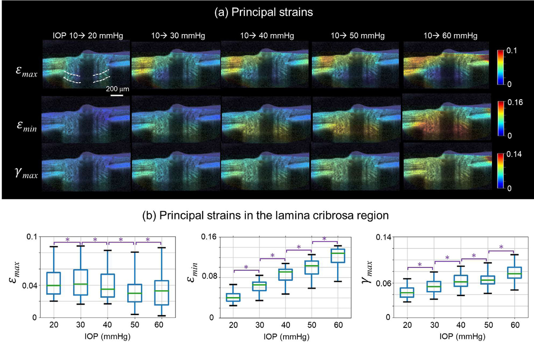
The IOP-induced ONH deformations calculated by the proposed DVC method. (a) Example OCT B-scans colored by the principal strains as IOP increased from 10 to 20, 30, 40, 50, and 60 mmHg, respectively. The lamina cribrosa region is indicated by the white dashed lines. (b) Box plots of the principal strains in the lamina cribrosa region at different IOPs. The minimal principal strain (εmin) and the maximum shear strain (γmax) increased with IOP. We did not observe a clear trend of the maximum principal strain (εmax) in response to IOP elevations within the lamina cribrosa. * significantly different (p < 0.05).
4. Discussion
Accurate characterization of ONH deformations between OCT volumes depends upon high-quality DVC. However, due to challenges in image registration, high noise, unclear accuracy, and considerable computational burden, existing DVC methods often fall short. Our goal was to introduce a revised DVC method that addresses the shortcomings of existing DVC methods through a combination of technical improvements. Specifically, there are five improvements of the proposed method compared to the conventional method: First, a pre-registration technique was used to remove the large ONH rigid body motion in OCT volumes which could otherwise lead to analysis failure; second, a modified 3D IC-GN method was used to ensure the sub-voxel accuracy of the displacement calculations despite high noise and low image contrast of some OCT volumes; third, a tricubic B-spline interpolation method was applied to improve the computational efficiency; fourth, a confidence parameter was introduced to guide the searching path in the displacement calculation; fifth, a confidence-weighted strain calculation method was applied to further improve the accuracy.
Four main contributions arise from this work: 1) image pre-registration corrected ONH rigid body motion well; 2) sub-voxel registration was achieved via a modified 3D IC-GN method, 3) the computational burden was dramatically reduced through use of a custom look-up table and occupied memory was saved, and 4) our DVC method was computationally efficient and can achieve sub-voxel accuracy in displacement calculation and 10−3 accuracy in strain calculation The synthesis of these contributions resulted in improved DVC measurement quality and workflow efficiency in real-world application. Below we discuss each of these in more detail.
Contribution 1: Image pre-registration corrected ONH rigid body motion well
No two OCT scans are of precisely the same region in the same orientation, even when the subject is anesthetized. Eye-tracking software of some OCT systems can help reduce motion, but often there are still differences in the location or orientation of the scanned region, for example by breath or pulse, sometimes resulting in considerable ONH rigid body motion between the reference and deformed volumes. If substantial rigid body rotations remain, it could lead to failure of the DVC algorithm. Large displacements reduce computational efficiency. Reported DVC methods did not mention efforts to account for the issue of rigid body motion [7, 30, 42, 44].
We have shown that our semiautomatic pre-registration technique works well to correct ONH rigid body motion. When the ONH has a large rotation (more than 4°) between the reference and deformed volumes, manual operation was necessary; otherwise, the automatic correction would fail. Manual operation is easy and convenient due to the relatively large rotation angle error tolerance (about 2°), the developed user-friendly interactive software and the distinct edge features in the ONH, like the Bruch’s membrane. Phase correlation and Nelder-Mead nonlinear optimization were then used to further automatic calculate the rigid body motion. The deformed volume registered well to the reference volume after pre-registration. The absolute rotation angle differences (Δθx, Δθy, Δθz) were all less than 0.4° This technique has the voxel-level translation accuracy, which can explain why all the absolute translation differences (ΔTx, ΔTy, ΔTz) were 0.3 voxels in the tests.
Contribution 2: Sub-voxel registration was achieved via a modified 3D IC-GN method
After image pre-registration minimized rigid body motion, a coarse search was done first to locate the corresponding point with voxel level accuracy. Bar-Kochba et al [44]. implemented a coarse search process of DVC in the Fourier frequency domain as it can greatly enhance the search efficiency. However, search accuracy decreases considerably if the deformation is larger than 7%. In practice, the ONH may be subjected to deformations of more than 10% in response to elevated IOP. Hence, our coarse search process was performed in the spatial domain to ensure accuracy despite its low efficiency. Then, the popular 3D IC-GN iteration method was used to obtain the deformation parameter p including displacement vector of sub-voxel accuracy by minimizing the ZNSSD coefficient.
Girard et al [7]. directly applied a genetic optimization algorithm to determine the deformation gradient tensor and displacement vector by minimizing the ZNSSD coefficient. This method can achieve high accuracy, but its computational efficiency is very low, i.e., 15 h to process 10,000 POIs. Compared with the genetic optimization algorithm which was directly applied to determine the deformation gradient tensor and displacement vector by minimizing the ZNSSD coefficient [7], 3D IC-GN has substantially higher computation efficiency, i.e., less than 18 min to process 27,000 POIs. OCT images can have low contrast and considerable noise.
Even when the OCT instrument’s signal averaging function is used, the acquired volumes in our practical applications still have relatively high noise level. This issue hinders the convergence of 3D IC-GN iteration. When it fails to converge, we selected the p at the iteration step having the minimal ‖Δp‖ instead of the minimal CZNSSD in order to ensure sub-voxel accuracy of DVC. ‖Δp‖ was likely to be at its minimum when p most approaches the exact value in the iteration process, whereas, the difference of CZNSSD is negligible, which can also explain why the convergence condition is set based on ‖Δp‖ instead of CZNSSD.
With the help of the modified 3D IC-GN method, our proposed DVC method can achieve sub-voxel accuracy in translation measurement. The average absolute displacement errors in the X, Y, and Z directions were very similar, under 0.028 voxels with speckle noise and under 0.037 voxels with Gaussian noise, indicating its isotropic accuracy in the three directions. The respective average, absolute, and relative strain errors in these three directions were less than 0.0018 and 4% with speckle noise, and less than 0.0045 and 8% with Gaussian noise. Gaussian noise had a more negative effect on DVC accuracy than the same level of speckle noise. In fact, speckle noise of OCT volumes was substantially larger than Gaussian noise. As a result, the former practically results in greater DVC measurement error than the latter.
Contribution 3: Computational burden of non-integer voxel interpolation was reduced by a custom look-up table and occupied memory was saved
Conventional DVC is computation- and time-intensive partly because of a large number of interpolations which are required with sub-voxel registration to calculate non-integer voxel intensities. In each iteration, the number of interpolations is equal to the size of subvolume, up to 12,000 non-integer voxel interpolations in this work. In other studies, a trilinear interpolation method was employed due to its high computational efficiency and ease of implementation [7, 44]. Yet, its interpolation error is not negligible. The popular higher-order tricubic B-spline interpolation method was used in this DVC method because of its reduced interpolation error, but its main shortcoming has very low computational efficiency. To speed up computation, we built a look-up table to save the results of the first three multiplication factors of Eq. (8). This look-up table was independent of the processed OCT volume and only occupied 0.61 MB. Each non-integer voxel interpolation in our method consisted of 84 multiplications and 63 additions. Optimized computation dramatically increased DVC efficiency by more than 50% and saved the memory by about 30%, comparing with the conventional method using a look-up table of B-spline control points (more than 800 MB memory, 212 multiplications and 155 additions) [42] and conventional method using a look-up table of 64 interpolation coefficient (more than 50 GB, 192 multiplications and 63 additions) [30]. If higher resolution OCT volumes are used, the proposed interpolation method would have a more direct advantage as its look-up table is independent of the volume and remains the same, whereas, the conventional methods would consume more memory.
Contribution 4: Our DVC method was computationally efficient and can achieve sub-voxel accuracy in displacement calculation and 10−3 accuracy in strain calculation
With rigid body motion, the overall performance of our DVC method had fairly considerable advantages over the conventional DVC method in displacement and strain measurement accuracy, and computation efficiency. Our DVC method had overall displacement errors smaller than 0.05 voxel with speckle noise and 0.07 voxel with gaussian noise, and the overall strain errors of under 0.0025 with speckle noise and 0.006 with Gaussian noise. Overall displacement and strain errors of our DVC method were less than 1/3 of the conventional method. Besides, our DVC method takes less than 18 min to process 27 000 POIs; the computation efficiency was enhanced by about 75%. If the rotation angle is relatively large, i.e., up to 7°, the conventional DVC method would fail to work, whereas, it would not affect the proposed DVC method because of the presented pre-registration technique.
The high accuracy of our DVC method was also partly the result of the confidence-guided searching strategy and confidence-weighted strain calculation: 1) the number of low reliable POIs misused to guide the searching path in our method was decreased to under 1/3 of that of conventional correlation-coefficient-guided searching strategy; and the strain obtained from the confidence weighted strain calculation method was also more accurate than the conventional strain calculation method. The confidence was defined by considering both image contrast of subvolume and correlation coefficient.
Application of our DVC method
In application, our DVC method produced measurements of IOP-induced ONH deformations that were substantially less sensitive to noise or other artifacts than the conventional method. The measurements from our method were smoother, without what appear to be exaggerated strains in the conventional method results. We found that the minimal principal strain and the maximum shear strain in the lamina cribrosa region increased with IOP. Such information is critical to understand the role of IOP in altering the biomechanical environment within the ONH.
Recommendations
Our results show that, without applying any image pre-processing operations to OCT volumes, the proposed DVC method can still give reliable measures of the IOP-induced ONH deformations. Therefore, despite relatively large amplitude noise, we recommend against the use of OCT image pre-processing with this DVC method except for an image median filter. In particular, image contrast enhancement and histogram normalization should be avoided. These operations are useful for better visualization of OCT volumes, but they change the real voxel intensity variation information which may negatively affect the DVC accuracy.
Remaining challenges and considerations
There are some aspects of the proposed DVC method that deserve further consideration. The shadow of the blood vessels in the OCT volume is a challenging issue affecting the measurement accuracy of the POI near the shadow. Several previous studies have used compensation or similar techniques to reduce the shadows [45, 46]. It remains unclear how much the compensation may affect DVC-measured displacements and deformations within the shadows and deep within the tissues. We opted instead for identifying the shadow regions and removing them from analysis to attenuate their influence. Image segmentation along with morphological analysis, such as erosion and dilation, was adopted to separate the shadow from the ONH in this work. Nevertheless, it is difficult to choose the optimal threshold for segmentation: if the threshold is too large, some important regions may be missed; if it is too small, the shadow region is difficult to remove completely. Note that we did not apply any segmentations to the OCT volumes for our DVC method of calculating displacements. It may be possible to improve this process by using deep learning methods to separate out the shadows or use the OCT-angiography information from the same scans to predict the location of the most problematic shadows. Setting a relatively large size of the subvolume for correlation is also useful to minimize the influence of shadows.
It should be noted that the accuracy of the proposed DVC method was obtained without accounting for potential changes to the speckle pattern due to tissue deformation. It would be valuable to conduct a well-controlled ex vivo or phantom deformation experiment to test the accuracy of the method for strain measurement. However, such experiments are extremely difficult. Applying well-known, controlled deformations within a sample that faithfully represents the tissues of the posterior pole is not yet possible. A simpler surrogate or a phantom may be easier to control, but then it may not exhibit the realistic speckle behavior that includes subcellular structures. Thus, it is not yet possible to perfectly determine the accuracy of our DVC method accounting for all possible sources of speckle fluctuation.
It is important to consider that any DVC method, including the one we present here, could potentially induce some degree of ‘smoothing’ between tissue components that will depend on the size of the strain calculation box. A large size will result in the strain calculation being over-smoothed, whereas a small one will result in the strain calculation being sensitive to noise. In this study, the strain calculation box was set to 9 × 9 × 9, which can capture well the strain between larger neighboring components. Interestingly, for one of the key regions of interest, the lamina cribrosa, the majority of the scattering signal is from the beams. This is what makes it possible to distinguish the relatively dark pores from the beams. This means that the calculations of strain are primarily representative of the beams, without any substantial smoothing. In other regions with more uniform signal profiles there may be some smoothing between adjacent tissues.
Readers interested in using our algorithm should note that the parameters we have reported herein were determined and tested for our specific OCT system. It is possible that the numbers may have to be adjusted for other systems. For example, Tcorr may be closer to 0.65 if the image quality is low, or closer to 0.80 if the image quality is high.
Another consideration is the manual component of our semiautomatic pre-registration technique. Effective manual operation more or less depends on the user’s experience to identify and coarsely align the ONH’s fairly apparent key features. To achieve fully automatic pre-registration, we may apply 3D scale-invariant feature transform (SIFT) [47] feature points to align the ONH in the future.
Lastly, we can perform the DVC technique in the graphics processing unit (GPU) platform to further improve its computational efficiency, although the proposed method has sped up the computation greatly compared with the conventional DVC method.
Summary
We present a high-accuracy and high-efficiency DVC technique to characterize in-vivo ONH deformations from OCT volumes. The method has been successfully applied to characterize the deformation of monkey ONHs subjected to acute and chronic IOP elevation [48, 49]. This technique has the potential to help investigate the pathologic mechanism of glaucoma and eventually, to help clinically diagnose glaucoma in its early stages. Although we demonstrate efficacy of this tool for images of the ONH, this DVC method can also be used to characterize the biomechanics of other biological tissues [50–52].
Supplementary Material
Statement of significance.
The biomechanics of the optic nerve head (ONH) in the posterior pole of the globe play a central role in eye physiology and pathology. The application of digital volume correlation (DVC) to the analysis of optical coherence tomography (OCT) images of the ONH has emerged as a promising way to quantify ONH biomechanics. Conventional DVC methods, however, face several important challenges when analyzing OCT images of the ONH. We introduce a high-accuracy and high-efficiency DVC method to characterize in vivo ONH deformations from OCT volumes. We demonstrate the new method using synthetic tests and actual OCT data from monkey ONHs. The new method also has the potential to be used to study other tissues, as OCT applications continue to expand.
Acknowledgement
Fengting Ji did the statistical analysis for the principal strains measured in the IOP-elevation-induced ONH deformation. We thank her for this work very much.
Funding
Supported in part by National Institutes of Health R01-EY023966, R01-EY025011, R01-EY028662, R01-EY030590, P30-EY008098 and T32-EY017271 (Bethesda, MD), the Eye and Ear Foundation (Pittsburgh, PA), and Research to Prevent Blindness.
Footnotes
Disclosure
Junchao Wei contributed to this work while he was at the University of Pittsburgh. He now works at Konica Minolta Laboratory. Other authors have no conflicts of interest.
Supplementary materials
Supplementary material associated with this article can be found, in the online version, at doi:10.1016/j.actbio.2022.02.021.
References
- [1].Campbell IC, Coudrillier B, Ross Ethier C, Biomechanics of the posterior eye: a critical role in health and disease, J. Biomech. Eng 136 (2) (2014) 021005. [DOI] [PubMed] [Google Scholar]
- [2].Ma Y, Kwok S, Sun J, Pan X, Pavlatos E, Clayson K, Hazen N, Liu J, IOP-induced regional displacements in the optic nerve head and correlation with peripapillary sclera thickness, Exp. Eye Res 200 (2020) 108202. [DOI] [PMC free article] [PubMed] [Google Scholar]
- [3].Quigley HA, Hohman RM, Addicks EM, Massof RW, Green WR, Morphologic changes in the lamina cribrosa correlated with neural loss in open-angle glaucoma, Am. J. Ophthalmol 95 (5) (1983) 673–691. [DOI] [PubMed] [Google Scholar]
- [4].Burgoyne CF, Downs JC, Bellezza AJ, Suh J-KF, Hart RT, The optic nerve head as a biomechanical structure: a new paradigm for understanding the role of IOP-related stress and strain in the pathophysiology of glaucomatous optic nerve head damage, Prog. Retin. Eye Res 24 (1) (2005) 39–73. [DOI] [PubMed] [Google Scholar]
- [5].Downs JC, Roberts MD, Sigal IA, Glaucomatous cupping of the lamina cribrosa: a review of the evidence for active progressive remodeling as a mechanism, Exp. Eye Res 93 (2) (2011) 133–140. [DOI] [PMC free article] [PubMed] [Google Scholar]
- [6].Midgett DE, Pease ME, Jefferys JL, Patel M, Franck C, Quigley HA, Nguyen TD, The pressure-induced deformation response of the human lamina cribrosa: analysis of regional variations, Acta Biomater. 53 (2017) 123–139. [DOI] [PMC free article] [PubMed] [Google Scholar]
- [7].Girard MJ, Strouthidis NG, Desjardins A, Mari JM, Ethier CR, In vivo optic nerve head biomechanics: performance testing of a three-dimensional tracking algorithm, J. R. Soc., Interface 10 (87) (2013) 20130459. [DOI] [PMC free article] [PubMed] [Google Scholar]
- [8].Sigal IA, Wang B, Strouthidis NG, Akagi T, Girard MJ, Recent advances in OCT imaging of the lamina cribrosa, Br. J. Ophthalmol 98 (Suppl 2) (2014) ii34–ii39. [DOI] [PMC free article] [PubMed] [Google Scholar]
- [9].Wang B, Nevins JE, Nadler Z, Wollstein G, Ishikawa H, Bilonick RA, Kagemann L, Sigal IA, Grulkowski I, Liu JJ, Reproducibility of in-vivo OCT measured three-dimensional human lamina cribrosa microarchitecture, PLoS One 9 (4) (2014) e95526. [DOI] [PMC free article] [PubMed] [Google Scholar]
- [10].Kim Y, Kim D, Jeoung J, Kim D, Park K, Peripheral lamina cribrosa depth in primary open-angle glaucoma: a swept-source optical coherence tomography study of lamina cribrosa, Eye 29 (10) (2015) 1368–1374. [DOI] [PMC free article] [PubMed] [Google Scholar]
- [11].Wu Z, Xu G, Weinreb RN, Yu M, Leung CK, Optic nerve head deformation in glaucoma: a prospective analysis of optic nerve head surface and lamina cribrosa surface displacement, Ophthalmology 122 (7) (2015) 1317–1329. [DOI] [PubMed] [Google Scholar]
- [12].Fazio MA, Johnstone JK, Smith B, Wang L, Girkin CA, Displacement of the lamina cribrosa in response to acute intraocular pressure elevation in normal individuals of African and European descent, Invest. Ophthalmol. Vis. Sci 57 (7) (2016) 3331–3339. [DOI] [PMC free article] [PubMed] [Google Scholar]
- [13].Ivers KM, Yang H, Gardiner SK, Qin L, Reyes L, Fortune B, Burgoyne CF, In vivo detection of laminar and peripapillary scleral hypercompliance in early monkey experimental glaucoma, Invest. Ophthalmol. Vis. Sci 57 (9) (2016) OCT388–OCT403. [DOI] [PMC free article] [PubMed] [Google Scholar]
- [14].Bedggood P, Tanabe F, McKendrick AM, Turpin A, Anderson AJ, Bui BV, Optic nerve tissue displacement during mild intraocular pressure elevation: its relationship to central corneal thickness and corneal hysteresis, Ophthalmic Physiol. Optics 38 (4) (2018) 389–399. [DOI] [PubMed] [Google Scholar]
- [15].Tan NY, Tham Y−C, Thakku SG, Wang X, Baskaran M, Tan MC, Mari J−M, Strouthidis NG, Aung T, Girard MJ, Changes in the anterior lamina cribrosa morphology with glaucoma severity, Sci. Rep 9 (1) (2019) 1–7. [DOI] [PMC free article] [PubMed] [Google Scholar]
- [16].Lee SH, Lee EJ, Kim JM, Girard MJ, Mari JM, Kim T−W, Lamina cribrosa moves anteriorly after trabeculectomy in myopic eyes, Invest. Ophthalmol. Vis. Sci 61 (6) (2020) 36–36. [DOI] [PMC free article] [PubMed] [Google Scholar]
- [17].Wong BJ, Moghimi S, Zangwill LM, Christopher M, Belghith A, Ekici E, Bowd C, Fazio MA, Girkin CA, Weinreb RN, Relationship of corneal hysteresis and anterior lamina cribrosa displacement in glaucoma, Am. J. Ophthalmol 212 (2020) 134–143. [DOI] [PMC free article] [PubMed] [Google Scholar]
- [18].Agoumi Y, Sharpe GP, Hutchison DM, Nicolela MT, Artes PH, Chauhan BC, Laminar and prelaminar tissue displacement during intraocular pressure elevation in glaucoma patients and healthy controls, Ophthalmology 118 (1) (2011) 52–59. [DOI] [PubMed] [Google Scholar]
- [19].Girkin CA, Fazio MA, Bowd C, Medeiros FA, Weinreb RN, Liebmann JM, Proudfoot J, Zangwill LM, Belghith A, Racial differences in the association of anterior lamina cribrosa surface depth and glaucoma severity in the African Descent and Glaucoma Evaluation Study (ADAGES), Invest. Ophthalmol. Vis. Sci 60 (13) (2019) 4496–4502. [DOI] [PMC free article] [PubMed] [Google Scholar]
- [20].Pan B, Wang B, Some recent advances in digital volume correlation, Opt. Lasers Eng 135 (2020) 106189. [Google Scholar]
- [21].Sigal IA, Grimm JL, Jan N−J, Reid K, Minckler DS, Brown DJ, Eye-specific IOP-induced displacements and deformations of human lamina cribrosa, Invest. Ophthalmol. Vis. Sci 55 (1) (2014) 1–15. [DOI] [PMC free article] [PubMed] [Google Scholar]
- [22].Wang X, Beotra MR, Tun TA, Baskaran M, Perera S, Aung T, Strouthidis NG, Milea D, Girard MJ, In vivo 3-dimensional strain mapping confirms large optic nerve head deformations following horizontal eye movements, Invest. Ophthalmol. Vis. Sci 57 (13) (2016) 5825–5833. [DOI] [PubMed] [Google Scholar]
- [23].Sibony PA, Gaze-evoked deformations in optic nerve head drusen, Invest. Ophthalmol. Vis. Sci 58 (8) (2017) 4310–4310.28800651 [Google Scholar]
- [24].Wang B, Tran H, Smith MA, Kostanyan T, Schmitt SE, Bilonick RA, Jan N−J, Kagemann L, Tyler-Kabara EC, Ishikawa H, In-vivo effects of intraocular and intracranial pressures on the lamina cribrosa microstructure, PLoS One 12 (11) (2017) e0188302. [DOI] [PMC free article] [PubMed] [Google Scholar]
- [25].Fazio MA, Clark ME, Bruno L, Girkin CA, In vivo optic nerve head mechanical response to intraocular and cerebrospinal fluid pressure: imaging protocol and quantification method, Sci. Rep 8 (1) (2018) 1–11. [DOI] [PMC free article] [PubMed] [Google Scholar]
- [26].Midgett DE, Quigley HA, Nguyen TD, In vivo characterization of the deformation of the human optic nerve head using optical coherence tomography and digital volume correlation, Acta Biomater. 96 (2019) 385–399. [DOI] [PMC free article] [PubMed] [Google Scholar]
- [27].Korneva A, Kimball EC, Jefferys JL, Quigley HA, Nguyen TD, Biomechanics of the optic nerve head and peripapillary sclera in a mouse model of glaucoma, J. R. Soc., Interface 17 (173) (2020) 20200708. [DOI] [PMC free article] [PubMed] [Google Scholar]
- [28].Fazio MA, Gardiner SK, Bruno L, Hubbard M, Bianco G, Karuppanan U, Kim J, El Hamdaoui M, Grytz R, Downs JC, Histologic validation of optical coherence tomography-based three-dimensional morphometric measurements of the human optic nerve head: methodology and preliminary results, Exp. Eye Res 205 (2021) 108475. [DOI] [PMC free article] [PubMed] [Google Scholar]
- [29].Zhong F, Quan C, Digital image correlation in polar coordinate robust to a large rotation, Opt. Lasers Eng 98 (2017) 153–158. [Google Scholar]
- [30].Wang T, Jiang Z, Kemao Q, Lin F, Soon SH, GPU accelerated digital volume correlation, Exp. Mech 56 (2) (2016) 297–309. [Google Scholar]
- [31].Wei J, Yang B, Voorhees AP, Tran H, Brazile B, Wang B, Schuman J, Smith MA, Wollstein G, Sigal IA, Measuring in-vivo and in-situ ex-vivo the 3D deformation of the lamina cribrosa microstructure under elevated intraocular pressure, Optical Elastogr. Tissue Biomech. V, Int. Soc. Optics Photonics (2018) 1049611. [Google Scholar]
- [32].Pan B, Wang B, Wu D, Lubineau G, An efficient and accurate 3D displacements tracking strategy for digital volume correlation, Opt. Lasers Eng 58 (2014) 126–135. [Google Scholar]
- [33].Fortune B, Burgoyne CF, Cull G, Reynaud J, Wang L, Onset and progression of peripapillary retinal nerve fiber layer (RNFL) retardance changes occur earlier than RNFL thickness changes in experimental glaucoma, Invest. Ophthalmol. Vis. Sci 54 (8) (2013) 5653–5661. [DOI] [PMC free article] [PubMed] [Google Scholar]
- [34].Sigal IA, Schuman JS, Ishikawa H, Kagemann L, Wollstein G, A problem of proportions in OCT-based morphometry and a proposed solution, Invest. Ophthalmol. Vis. Sci 57 (2) (2016) 484–485. [DOI] [PMC free article] [PubMed] [Google Scholar]
- [35].Reddy BS, Chatterji BN, An FFT-based technique for translation, rotation, and scale-invariant image registration, IEEE Trans. Image Process 5 (8) (1996) 1266–1271. [DOI] [PubMed] [Google Scholar]
- [36].Meng F, Chen C, Hui S, Wang J, Feng Y, Sun C, Three-dimensional static optical coherence elastography based on inverse compositional Gauss-Newton digital volume correlation, J. Biophotonics 12 (9) (2019) e201800422. [DOI] [PubMed] [Google Scholar]
- [37].Pan B, Wang B, A flexible and accurate digital volume correlation method applicable to high-resolution volumetric images, Meas. Sci. Technol 28 (10) (2017) 105007. [Google Scholar]
- [38].Luu L, Wang Z, Vo M, Hoang T, Ma J, Accuracy enhancement of digital image correlation with B-spline interpolation, Opt. Lett 36 (16) (2011) 3070–3072. [DOI] [PubMed] [Google Scholar]
- [39].Pan B, Lu Z, Xie H, Mean intensity gradient: an effective global parameter for quality assessment of the speckle patterns used in digital image correlation, Opt. Lasers Eng 48 (4) (2010) 469–477. [Google Scholar]
- [40].Sousa PJ, Tavares JMR, Tavares PJ, Moreira PM, Correction of rigid body motion in deformation measurement of rotating objects, Measurement 129 (2018) 436–444. [Google Scholar]
- [41].Schmitt JM, Xiang S, Yung KM, Speckle in optical coherence tomography: an overview, Saratov Fall Meeting’98: light Scattering Technologies for Mechanics, Biomed. Mater. Sci. Int. Soc. Optics Photonics (1999) 450–461. [Google Scholar]
- [42].Pan B, Wu D, Wang Z, Internal displacement and strain measurement using digital volume correlation: a least-squares framework, Meas. Sci. Technol 23 (4) (2012) 045002. [Google Scholar]
- [43].Tran H, Grimm J, Wang B, Smith M, Gogola A, Nelson S, Tyler-Kabara E, Schuman J, Wollstein G, Sigal I, Mapping in-vivo optic nerve head strains caused by intraocular and intracranial pressures, Optical Elastogr. Tissue Biomech. IV, Int. Soc. Optics Photonics (2017) 100670B. [DOI] [PMC free article] [PubMed] [Google Scholar]
- [44].Bar-Kochba E, Toyjanova J, Andrews E, Kim KS, Franck C, A fast iterative digital volume correlation algorithm for large deformations, Exp. Mech 55 (1) (2015) 261–274. [Google Scholar]
- [45].Girard MJA, Strouthidis NG, Ethier CR, Mari JM, Shadow removal and contrast enhancement in optical coherence tomography images of the human optic nerve head, Invest. Ophthalmol. Vis. Sci 52 (10) (2011) 7738–7748. [DOI] [PubMed] [Google Scholar]
- [46].Girard MJA, Tun TA, Husain R, Acharyya S, Haaland BA, Wei X, Mari JM, Perera SA, Baskaran M, Aung T, Strouthidis NG, Lamina cribrosa visibility using optical coherence tomography: comparison of devices and effects of image enhancement techniques, Invest. Ophthalmol. Vis. Sci 56 (2) (2015) 865–874. [DOI] [PubMed] [Google Scholar]
- [47].Niemeijer M, Garvin M, Lee K, van Ginneken B, Abràmoff M, Sonka M, Registration of 3D Spectral OCT Volumes Using 3D SIFT Feature Point Matching, SPIE, 2009. [Google Scholar]
- [48].Sigal IA, Zhong F, Hua Y, Wei J, Bansal M, Reynaud J, Fortune B, In-vivo evidence of lamina cribrosa deformations induced by chronically elevated IOP in non-human primates, Invest. Ophthalmol. Vis. Sci 62 (8) (2021) 1862–1862. [Google Scholar]
- [49].Zhong F, Hua Y, Wei J, Bansal M, Reynaud J, Fortune B, Sigal IA, In-vivo evidence of increased lamina cribrosa compliance at onset of experimental glaucoma in nonhuman primates, Invest. Ophthalmol. Vis. Sci 62 (8) (2021) 1827–1827. [Google Scholar]
- [50].Disney CM, Eckersley A, McConnell JC, Geng H, Bodey AJ, Hoyland JA, Lee PD, Sherratt MJ, Bay BK, Synchrotron tomography of intervertebral disc deformation quantified by digital volume correlation reveals microstructural influence on strain patterns, Acta Biomater. 92 (2019) 290–304. [DOI] [PubMed] [Google Scholar]
- [51].Acosta Santamaría VA, García MF, Molimard J, Avril S, Characterization of chemoelastic effects in arteries using digital volume correlation and optical coherence tomography, Acta Biomater. 102 (2020) 127–137. [DOI] [PubMed] [Google Scholar]
- [52].Midgett DE, Jefferys JL, Quigley HA, Nguyen TD, The inflation response of the human lamina cribrosa and sclera: analysis of deformation and interaction, Acta Biomater. 106 (2020) 225–241. [DOI] [PMC free article] [PubMed] [Google Scholar]
Associated Data
This section collects any data citations, data availability statements, or supplementary materials included in this article.