. 2021 Oct 5;11(52):32750–32774. doi: 10.1039/d1ra04890b

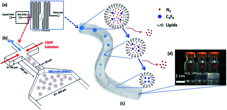
Fig. 20. A microfluidic nanobubble generator that is recently reported by our group. (a) Top-view schematic diagram of the microfluidic chip, showing liquid (lipid solution), gas and reservoir inlets. The serpentine structure of the design facilitates the tracking of microbubble shrinkage into nanobubbles by a microscope. (b) The flow-focusing section of the microfluidic chip to generate monodisperse microbubbles. The width and length of the orifice are 20 μm and 100 μm, respectively. Following the generation of the microbubbles, the shrinkage process begins with the entry of the microbubbles into the serpentine microchannel. The width of this microchannel is 350 μm, and the height of all channels in the device is 50 μm. (c) The gradual outflow of nitrogen from the cores of microbubbles and dissolution into the aqueous phase leads to microbubble shrinkage. In contrast, C3F8 remains inside the bubble's core due to its low solubility. (d) Three different samples are taken from the reservoir inlet. Sample 1 is the control group consisting of lipid solution, and samples 2 and 3 contain bulk nanobubbles with mean diameters of 100 nm and 200 nm, respectively.149.

Fig. 20