. 2020 Feb 24;10(13):7956–7966. doi: 10.1039/d0ra00115e

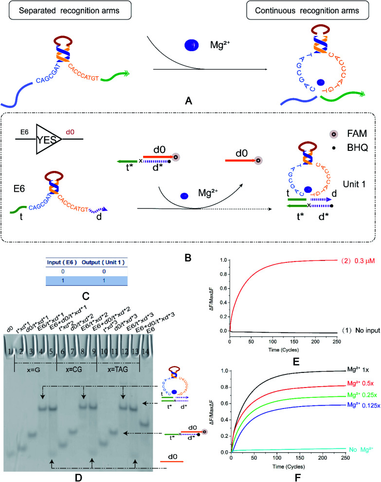
Fig. 1. (A) The DNAzyme recognition arms undergo a conformational change under the control of Mg2+. (B) YES logic gate reaction schematic. The 3′ end of d0 in the double-stranded substrate modifies the fluorophore FAM, and the 5′ end of t*d* modifies the quenching group BHQ. The E6 DNAzyme recognition arms undergo a strand displacement reaction with a double-stranded substrate and binds to t*d* therein to release a fluorescent signal. (C) YES logic gate corresponding to the logical operation truth table. (D) Native PAGE analysis of the YES logic gate. The number is marked above each lane, and the top is the DNA strand type for each lane. Lane 1: d0; lane 14: E6 DNAzyme; lane 1: d0; lane 14: E6 DNAzyme; The 2–14 lanes are divided into three parts, which are three implementation methods of the YES logic gate. The bases of the “x” in the DNA strand t*xd * are “G”, “CG”, and “TAG”. Lanes 2, 6, and 10 are t*xd*; lanes 3, 7, and 11 are the double strands synthesized by t*xd* and d0 ([t*xd*] : [d0] = 1 : 1.1). Lanes 4, 8 and 12 are structures formed by annealing E6 with t*xd* ([E6] : [t*xd*] = 1 : 1.1), and are also strands for comparison with the results. Lanes 5, 9, and 13 are the logical gates for the reaction of the E6 DNAzyme with the double-stranded substrate ([E6] : [t*xd*/d0] = 1 : 1). (E) YES logic gate normalized to the fluorescence intensity curve, solution concentration is 0.3 μm, sampling scan interval time was set to 6 s, for a total of 251 cycles. (F) Normalized fluorescence curve of YES logic gate fluorescence intensity as a function of Mg2+ concentration. All data represent the average of three replicates, and the error bar represents one standard deviation representing three replicated analyses.

Fig. 1