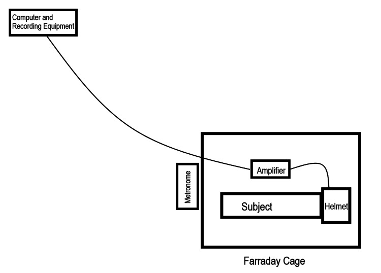
Figure 2. Diagram of a subject within the recording setup.
Diagram is not drawn to scale. Within the area labeled "Helmet," electromagnetic field channels were connected to the helmet construct with the sensors placed within each channel. Thin lines connecting the helmet to the amplifier and gain filter module and from the amplifier to the computer and recording equipment represent wires connecting the devices.

