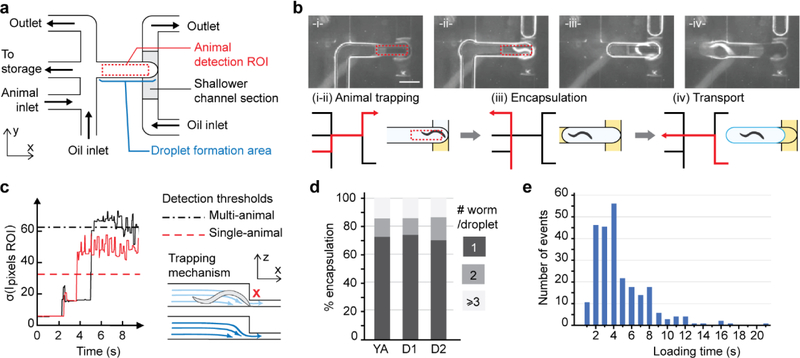
Figure 2.
Active in-situ droplet production unit for efficient single-animal encapsulation. (a) Microfluidic network layout. The sequential flow pattern is controlled using a set of valves upstream of the channels (not shown on the schematics). (b) Top: Representative pictures of the sequential flow routine (scale bar is 800 μm). Bottom: schematic of the encapsulation process. For each step, the active flow path is indicated in red. (i-ii) The aqueous phase flows through the trapping chamber until an animal is detected. (iii)The oil flow segments the aqueous droplet encapsulating the animal. The rear interface is created by actively flowing oil, while, on the front side, the aqueous film in the shallower channel section breaks spontaneously. (iv) The droplet is pushed outside the trapping chamber for further processing. (c) The trapping mechanism is based on the physical constriction of the channel. Real-time image processing of the animal detection ROI allows for the immediate detection of a trapped animal: The signal takes the characteristic shape of a near-zero level, brief peak, plateau, and a sudden prolonged increase corresponding respectively to the oil phase filling the chamber, water-oil interface passing, water-filled chamber state, and finally the presence of a trapped animal. (d) Single animal encapsulation performance; (e) Animal loading time is ~ 4 s long, ensuring a time-efficient encapsulation process.

