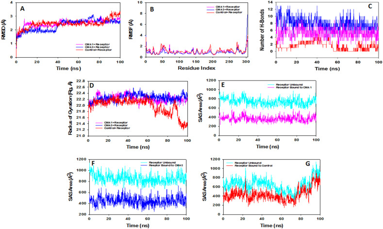
Fig. 6.
Analysis of MD simulation trajectories of 100 ns time scale. (A) RMSD plot displaying the molecular vibration of Cα backbone of Receptor + control (red), Receptor + CMA1 (pink) and Receptor + CMA3 (blue). (B) RMSF plots showing the fluctuations of respective amino acids throughout the simulation time 100 ns for Receptor + control (red), Receptor + CMA1 (pink) and Receptor + CMA3 (blue). (C) Number of hydrogen bonds formed between Receptor + control (red), Receptor + CMA1 (pink) and Receptor + CMA3 (blue) during 100 ns simulation time scale. (D) Radius of gyration plots for the deduction of compactness of protein Receptor + control (red), Receptor + CMA1 (pink) and Receptor + CMA3 (blue). Solvent accessible surface area (SAS Area) displaying the ligand bound and unbound area at the binding pocket (cyan), (E) Receptor + CMA1 (pink), (F) Receptor + CMA3 (blue) and (G) Receptor + control (red).

