
Figure 7.
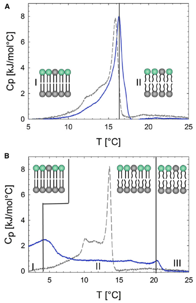
DSC cooling scans of aLUVs. Solid blue lines show DSC profiles of aLUVs prepared at a donor:acceptor ratio of 3:1. Dashed gray lines represent a scrambled lipid composition, where the aLUV lipids are mixed, resulting in symmetric LUVs. (A) DSC profiles of aLUVS with POPE in the inner leaflet and POPE:POPC in the outer leaflet. The regions (I) and (II) represents gel and fluid phase bilayers, respectively. Insets to the figure show schematics of gel and fluid phase bilayers. (B) DSC profiles of aLUVs with POPC in the inner leaflet and POPE:POPC in the outer leaflet. The DSC profile of aLUVs (solid blue line) can be described by three different regions. Region (I) represents gel phase bilayers. Region (II) corresponds to a co-existence of gel and fluid phase bilayers. Finally, in region (III), the bilayers are all in the fluid phase. Note that because lipid exchange efficiency is not 100%, the composition of the outer leaflet is a mixture of POPE:POPC. Adapted from [54].