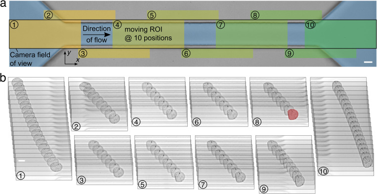
FIG. 1.
Dynamic tracking of single cells in a microfluidic channel. (a) Image of a 30 × 30 μm2 microfluidic channel of 300 μm length. Overlaid sketch demonstrates the principle of dynamic cell tracking. Camera field of view is indicated by a black rectangle covering the complete length of the channel as well as the inlet and outlet regions. A moving cell is tracked by a moving region-of-interest (ROI, 250 × 100 pixels) shifted stepwise in the direction of flow depending on the cell position inside the channel (ROI positions 1–10 are highlighted). (b) Image sequence of a tracked HL60 cell captured over time consisting of 98 consecutive frames. The trace was captured at the ten different ROI positions indicated in (a). The cell shape at the end of the channel is highlighted in red and scale bars are 10 μm. Flow rate was set to 8 nl s−1.

