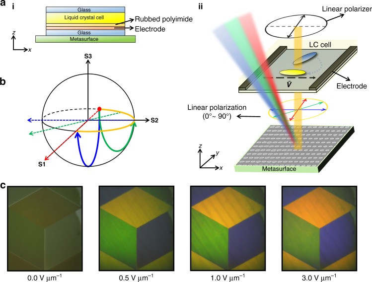
Fig. 4. Liquid crystal design and integration.
a Schematic illustration of the LC integrated metasurface. (ii) Incident LP is modulated through the LC cell. The orientation of LCs at E = 0.0 and =3.0 V µm−1 is denoted by blue and yellow molecules, respectively. b Poincare sphere representing the change in LP state. The solid blue and green lines describe the polarization transitions at E = 0.0 and 0.4 V µm−1, respectively, with the rotation axis of the Poincare sphere (dotted lines). The orange line indicates the range of LP states that we manipulate. c Experimental demonstration of electrically tunable cryptographic images using LC integrated polarization sensitive metasurfaces. The brightness of the image is electrically tuned from dark black to bright colors using an external bias from E = 0.0 to 3.0 V µm−1

