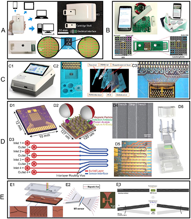
Figure 8.
(A–C) Photographs (and drawings) of three GMR POC devices reported by different groups. (D) (D3, D5) Microfluidic channels D3 and D5 (D1) aligned on the GMR sensor arrays with the sensor array compartmentalized into four complementary independent compartments. (D2) Sandwich assay. (D4) SEM image of MNP labels on GMR sensor stripes. (D6) Schematic view of cartridge integrating microfluidic chip and sensor array. (E1) Microfabricated micropillar arrays for on-chip filtering that is compatible with a microfluidic chip. (E2) (Left) Schematic view of MFC to amplify the magnetic field in the sensor region (left) and (right) a photograph of a pair of microfabricated MFCs. (E3) Schematic view of cantilever mechanical movement induced AC magnetic field in the GMR sensor region. (A) Reprinted with permission from ref 96. Copyright 2017 American Chemical Society. (B) Reprinted with permission from ref 97. Copyright 2021 Elsevier B.V. (C) Reprinted with permission from ref 73. Copyright 2018 Elsevier B.V. (D) Reprinted with permission from ref 100. Copyright 2015 The Royal Society of Chemistry. (E1) Reprinted with permission from ref 74. Copyright 2018 The Royal Society of Chemistry. (E2) Reprinted with permission from ref 101. Copyright 2020 Elsevier B.V. (E3) Reprinted from ref 102. Licensed under CC BY 4.0.

