Abstract
B, N dual-doped sisal-based activated carbon (BN-SAC) with a multiscale porous structure for high-rate supercapacitor electrode was prepared through a novel and facile strategy. With the inherent cellular channels serving as primary macropores, secondary mesopores and micropores are generated on the fiber surface and tracheid walls through low-pressure rapid carbonization of (NH4)2B4O7-containing sisal fibers and successive KOH activation. In addition to introducing B, N atoms into the BN-SAC, the additive also facilitates the formation of mesopores due to the rapid gas evaporation during its decomposition, leading to significantly increased specific surface area (2017 m2 g−1) and mesoporosity (68.6%). As a result, the BN-SAC-3 shows highly enhanced electrochemical performance including a high specific capacitance of 304 F g−1, excellent rate capability (with 72.6% retention at 60 A g−1) and superior cycling stability (4.6% capacitance loss after 3000 cycles). After assembling the BN-SAC-3 into symmetric supercapacitor, it shows a specific capacitance of 258 F g−1 at 1 A g−1 with 76.4% retention at 40 A g−1 in 6 M KOH electrolyte, and delivers a maximum energy density of 24.3 W h kg−1 at a power density of 612.8 W kg−1 in 1 M TEABF4/AN electrolyte. This work provides a new strategy for the synthesis of multiscale porous ACs for high-performance supercapacitors or other energy storage and conversion devices and is expected to be applied on other biomasses for large-scale production.
B, N dual-doped sisal-based activated carbon (BN-SAC) with a multiscale porous structure for high-rate supercapacitor electrode was prepared through a novel and facile strategy.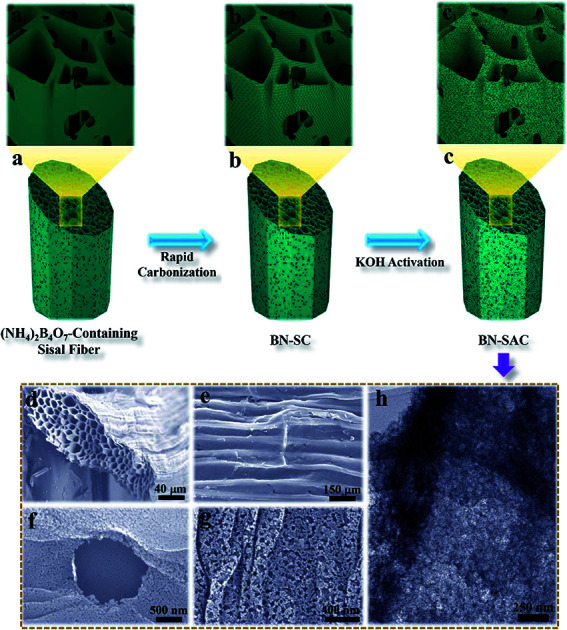
1. Introduction
With higher power density than batteries, higher energy density than traditional electrostatic capacitors, superior charge–discharge rate, excellent cycling stability and good durability, electric double-layer capacitors (EDLCs, also called supercapacitors) have gained huge attention and have been successfully applied in a variety of systems including electrical vehicles, uninterruptible power supplies, emergency doors and portable electronic devices.1,2 As EDL capacitance is in direct proportion to the effective surface area of electrode on which electrolyte ions could be absorbed, carbon-based materials including activated carbons (ACs), carbon nanofibers (CNFs), templated carbons, carbon aerogels (CAs), carbon nanotubes (CNTs) and graphene have been intensively investigated as electrode materials in EDLCs due to their high specific surface area (SSA) as well as superior electrical conductivity and chemical inertness.3–8 With low cost and large-scale industrial production, ACs-based electrodes are preferred by most commercially available supercapacitors.9,10 Nevertheless, the ACs produced by common physical or chemical activation always possess disordered porous textures and abundant small micropores (mainly <0.6 nm) both of which would significantly reduce the accessible surface area for electrolyte ions.11,12 As a result, the ACs-based electrodes typically show limited specific capacitance (<10 μF cm−2) and inferior rate capability (sharply reduced specific capacitance at high current densities), despite having ultrahigh SSA of up to 2000–3000 m2 g−1.13,14 To solve these problems, efforts have been devoted on novel preparation methods combining various pretreatment processes and common activation to produce ACs with both high SSA and high ratio of mesopores, thus resulting in high specific capacitance and high rate performance.15–19 For example, through combining hydrothermal and KOH activation, ACs with high SSA (3037 m2 g−1) and high mesoporosity (>82%) were prepared from lotus pollen, and exhibited a high capacitance of 207 F g−1 and superior capacitance retention of about 190 F g−1 at 10 A g−1.10 However, in spite of the ratios of meso/micropore are tunable in these novel ACs, the disordered pore structures with randomly distributed mesopores and micropores still hinder the full utilization of all-level pores.
Recent molecular dynamic simulations and experimental results suggest that carbon materials with multiscale pores, especially with hierarchical macro–meso–microporous structures can facilitate ion diffusion at ultrahigh current densities.20–22 With primary macropores serving as electrolyte reservoirs and secondary mesopores as buffer zone, the unobstructed hierarchical channels with highly shorted diffusion distance make the diffusion of ions into/out of the nearby micropores easier and rapider, giving rise to outstanding capacitance and rate capability.23,24 Previous attempts on achieving such multiscale porous structures always rely on complicated and uneconomical template method.22,25 With the rapid development of nanocarbon materials such as CNTs and graphene, creating regular macroscopic assembles including fibers, films and foams with individual CNTs and graphene seem to be another promising way for multiscale porous structures.26–28 Unfortunately, these nano-sized individuals always encounter with problems such as high cost and inevitable agglomeration during assembling.2,29 In addition, the relatively low density of electrodes based on CNTs and graphene also restrict their wider application in EDLCs due to lower volumetric specific capacitance compared with ACs.30 Therefore, it is highly demanded to develop novel preparation methods for ACs with both high SSA and hierarchical multiscale porous structures, especially in a simple and economical way.
Besides optimizing porous structure, heteroatoms doping (i.e., nitrogen (N), oxygen (O), boron (B), phosphorus (P), sulfur (S) doping) has also been regarded as an effective method to improve the electrochemical performance of ACs, owing to the introduced pseudocapacitance, increased electrical conductivity and improved surface wettability of pore walls.31–36 Compared with single-atom doping, recent researches focus more on dual-atom doping as which could take advantages of two different heteroatoms in addition to inducing synergistic effect.37–39 In fact, it has been proven that B, N dual-doping could remarkably increase the surface area, active sites and interlayer distance of carbon.40,41 As a result, it seems to be an ideal strategy to co-dope B and N atoms into multiscale porous ACs for high-performance EDLCs electrodes.
Benefiting from their high yield, cost effectiveness and environmental friendliness, biomasses have widely been employed as precursors for ACs.42–47 As one promising but less explored biomasses for such application, sisal fibers simultaneously possess high tensile strength, high ratio of length to diameter, high yield of carbonization and short growth periodicity.45,46 Different from various natural fibers such as jute, flax, hemp, cotton and ramie, sisal fibers are especially characterized with honeycomb texture constructed by abundant parallel distributed tracheids.15–17 The unique honeycomb structure is quite beneficial for the development of hierarchical porous structure, while previous studies merely employed sisal fibers as common precursors of ACs.44,46,48–50 Herein, for the first time, we report a novel method to prepare B, N dual-doped ACs with multiscale porous structure from sisal fibers for high-performance EDLCs. With unique cellular channels serving as primary macropores, secondary mesopores are generated on fiber surface and tracheid walls through rapid carbonization of sisal fibers with B, N-containing reagent under low pressure, followed by KOH activation which further create micropores on mesopore walls. Notably, the infiltrated (NH4)2B4O7 not only endow the as-obtained ACs with B, N dual-doping, it also facilitates the formation of secondary mesopores due to the rapid gas evaporation during its decomposition. Benefitting from their hierarchical macro–meso–microporous structure with both high SSA and mesoporosity, as well as B, N dual-doping which provides pseudocapacitance and improves electrical conductivity, the BN-SAC-3 exhibits excellent electrochemical performance including a high specific capacitance of 304 F g−1 at 1 A g−1 with 72.6% retention at 60 A g−1 and excellent cycling stability (4.6% capacitance loss after 3000 cycles). Moreover, the BN-SAC-3 in a symmetric supercapacitor with 6 M KOH as electrolyte shows a specific capacitance of 258 F g−1 at 1 A g−1 with 76.4% retention at 40 A g−1, and delivers a maximum energy density of 24.3 W h kg−1 at a power density of 612.8 W kg−1 in 1 M TEABF4/AN electrolyte.
2. Experimental section
2.1. Materials
Unbleached sisal fibers were purchased from Guangdong Dongfang Sisal Group Co. Ltd. (China). Before use, the fibers were boiled with deionized water for 2 hours. (NH4)2B4O7·4H2O (AR, Sigma-Aldrich), potassium hydroxide (AR, Sigma-Aldrich), carbon black (TIMCAL SUPER P LI), poly-tetrafluoroethylene (PTFE, DAIKIN), tetraethylammonium-tetrafluoroborate/acrylonitrile (TEABF4/AN, CAPCHEM) and separator films (MPF30AC and TF4840, NKK) were all used as received.
2.2. Fabrication of the BN-SAC-n
The sisal fibers were cut into short fibers (∼30 mm length) and immersed into aqueous solution of (NH4)2B4O7·4H2O (0.04, 0.08 and 0.16 M) for one day under continuous stirring at room temperature. After the sisal fibers were fully dried in an electric oven, they were subjected to a two-step process to prepare BN-SAC-n. First, 3.0 g of sisal fibers were placed in a rapid thermal processing furnace (BTF-1200C-RTP-S90B, 10 kW, AnHui BEQ Equipment Technology Co., Ltd) powered by infrared-heating. Under continuous vacuuming for a low furnace pressure (below 10 kPa), the fibers were heated to 800 °C with a high heating rate of 100 °C min−1 and maintained for 2 h. The as-obtained products were then immersed in 1 M KOH aqueous solution overnight. After fully dried in an electric oven, the KOH-treated BN-SC were annealed in the same RTP at 800 °C for 1 h in flowing nitrogen atmosphere (with flow rate of 0.15 L min−1). After that, the sample was thoroughly washed with 1 M HCl and plenty of de-ionized water until the pH was 7. Finally, the product was dried at 90 °C overnight and denoted as BN-SAC-n, where n (1, 2 and 3) denotes the concentration of (NH4)2B4O7 aqueous solution (0.04, 0.08 and 0.16 M). For comparison, the sisal-based AC without B, N doping was prepared through traditional carbonization process (800 °C for 1 h with a heating rate of 5 °C min−1 under atmospheric pressure in flowing nitrogen atmosphere) and the same activation strategy, denoted as SAC.
2.3. Preparation of supercapacitor cells
The two-electrode symmetric supercapacitors (SSCs) with our BN-SAC-3 as active materials were fabricated as follows: active materials, carbon black and PVDF were homogeneously mixed with a mass ratio of 85 : 10 : 5 in the agate mortar, followed by casting the mixture on the current collectors (aluminum foil coated with carbon) with a thickness of 100–120 μm. After dried at 120 °C overnight under vacuum, the electrode were cut into round pieces with diameter of 16 mm and mass loading of about 1 mg cm−2. The prepared electrodes/collectors were then transferred into an Ar-filled glovebox (the content of water and oxygen were both controlled below 0.1 ppm) to symmetrically assemble two-electrode supercapacitors, employing 1 M TEABF4/AN as electrolyte and TF4840 as separator.
2.4. Physical characterization
The morphology of the samples was characterized with a Hitachi S-4700 Field Emission Scanning Electron Microscopy (FESEM) at an acceleration voltage of 15 kV and a Themis Z F-30 Double Cs Corrector Transmission Electron Microscope (TEM) at an acceleration voltage of 300 kV. Nitrogen adsorption/desorption test was carried out with a Micromeritics ASAP 2020 apparatus at 77 K. The SBET was obtained using the Brunauer–Emmett–Teller (BET) method from adsorption data in the relative pressure (P/P0) ranging from 0.05 to 0.3, and the total pore volumes were acquired from the amount of nitrogen adsorbed at a relative pressure of 0.99. The pore size distribution, micropore volume and mesopore volume were calculated from the nitrogen adsorption/desorption data using the Non-Local Density Functional Theory (NL-DFT) software (SAIEUS, Micromeritics Instrument) with a ‘Heterogeneous Surface’ model. The X-ray diffraction (XRD) measurements were performed on a Bruker D8 Advance diffractometer with Cu Kα radiation (k = 0.1542 nm, 40 kV). The Raman spectra were obtained by a Renishaw-inVia Confocal Raman Microscope using excitation wavelength at 514.5 nm. The chemical composition was studied by X-ray photoelectron spectroscopy (XPS) using a Thermo Scientific X-ray photoelectron (K-alpha).
2.5. Electrochemical measurements
All the electrochemical measurements were carried out at room temperature. Before measurements, the working electrodes were soaked into 6 M KOH electrolyte overnight. For three-electrode test, the work electrode was prepared through coating the mixture consisting of active materials, PTFE (with a mass ratio of 90 : 10) and a small amount of ethanol onto nickel foam followed by drying it at 100 °C overnight, a Hg/HgO was employed as reference electrode and a platinum plate were employed as counter electrodes electrode, and 6 M aqueous KOH solution was used as electrolyte. The cyclic voltammetry (CV), galvanostatic charge–discharge and electrochemical impedance spectroscopy (EIS) analysis were all performed on a CHI660E electrochemical workstation (Shanghai Chen Hua Co., Ltd, China). The CV and galvanostatic charge–discharge tests were performed in a voltage window of −1.0 to 0 V vs. Hg/HgO electrode at scan rates of 10–400 mV s−1 and current densities of 1–60 A g−1, respectively. The EIS measurements were conducted under open circuit potential in the frequency range of 10 mHz to 100 kHz with 5 mV AC amplitude.
The specific capacitance (Cg, F g−1) of work electrode was calculated based on galvanostatic charge–discharge curves according to eqn (1) for three-electrode test and (2) for two-electrode test:
 |
1 |
 |
2 |
where I (A) is the discharge current, m (g) is the mass of active material in each work electrode, dv/dt is the slope of the discharge curve after voltage drop (IR drop). The energy density E (W h kg −1) and power density P (W kg −1) (based on the total mass of two electrodes) were calculated using the following equations of (3) and (4):
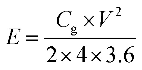 |
3 |
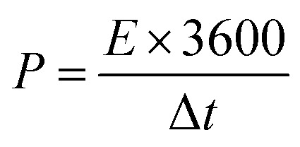 |
4 |
where V is the cell voltage after ohmic drop (V) and t is the discharge time (s).
3. Results and discussion
3.1. Fabrication of the BN-SAC-n
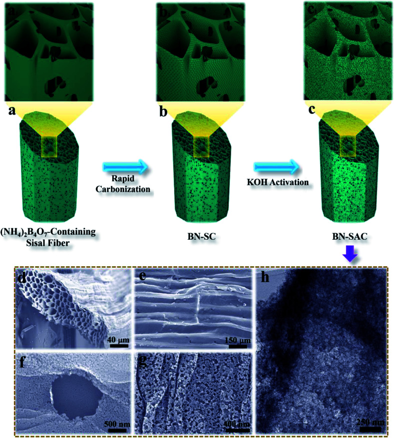
The schematic description of the fabrication process for BN-SAC-n, the SEM images and TEM image of BN-SAC-3 are illustrated in Fig. 1. As is shown, the (NH4)2B4O7-containing sisal fiber is characterized by typical honeycomb texture (Fig. 1a, a1 and d) inherited from raw sisal fibers (Fig. S2, ESI†) constructed by parallel distributed tracheids with abundant stomas (Fig. 1e) on both fiber surface and inner cellular walls. As the rapid gas evaporation from sisal fiber and (NH4)2B4O7 during low-pressure rapid carbonization is facilitated by the unique cellular structure and cannot be in consistent with the rate of fiber dimensional shrinkage, large mesopores and a few macropores are thus uniformly generated on the fiber surface and inner cellular walls (Fig. 1b, b1 and f–h). After further KOH activation, abundant micropores are etched on every surface of the fiber (Fig. 1h), resulting in a hierarchical macro–meso–microporous structure with undamaged fiber structural integrity.
Fig. 1. (a–c and a1–c1) Schematic illustration of the synthetic procedure for BN-SAC-n; (d–g) SEM images of the BN-SAC-3 showing the cross-section (d), surface with stomas (e) and magnified surface with a stoma (f) and macro/mesopores (g), TEM of the BN-SAC-3 showing the mesopores and micropores.
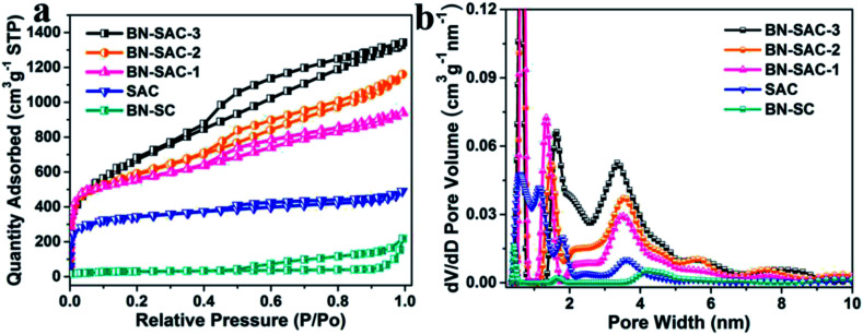
The detailed porous structure of all samples were studied by nitrogen adsorption–desorption technique (Fig. 2 and Table 1). As shown in Fig. 2a, the BN-SC shows characteristic type IV isotherm plots with an obvious hysteresis loop located at relative pressure (P/P0) between 0.5 and 1.0, indicating its well-developed mesoporous structure with a SSA of 94 m2 g−1 and mesoporosity of 93%.13,51 For the BN-SAC-n which went through further KOH activation, all profiles show hybrid type I/IV isotherm plots with evident hysteresis loops located at relative pressure (P/P0) higher than 0.4, indicating the formation of hierarchical macro–meso–microporous structures with abundant mesopores. Notably, as the amount of (NH4)2B4O7 increases, both of the hysteresis loops and slope of isotherm plots increase, suggesting the rapid development of mesopores and SSA in BN-SAC-n series. As shown in Table 1, the mesopore volume is 0.71 cm3 g−1 for BN-SAC-1, 1.09 cm3 g−1 for BN-SAC-2, and 1.33 cm3 g−1 for BN-SAC-3, while the micropore volume goes through slight decrease. As a result, the mesoporosity is significantly enhanced from 52.2 to 64.5 and 68.6% for BN-SAC-1, BN-SAC-2 and BN-SAC-3, respectively. In addition to mesopores, the corresponding SSA also increases with the doping level, going from 1802 m2 g−1 for BN-SAC-1, to 1978 m2 g−1 for BN-SAC-2, and 2017 m2 g−1 for BN-SAC-3. Possible explanation for this change is the gas evaporation from (NH4)2B4O7 decomposition is promoted at high concentration, resulting in more large pores and higher surface area both of which are beneficial for further KOH activation.40,41 The yield of sisal fibers after carbonization and activation is also in good accordance with the nitrogen adsorption–desorption tests, the yield of BN-SAC-1, BN-SAC-2 and BN-SAC-3 respectively decreases from 22.0 to 20.3 and 19.4% with the increasing concentration of (NH4)2B4O7. In contrast, the SAC prepared through traditional carbonization and activation shows typical type I isotherm plots characterized with microporous structure, exhibiting relatively low mesoporosity of 36.6% and SSA of 1017 m2 g−1, as well as a higher yield (27.6%) than BN-SAC-n series.
Fig. 2. (a) Nitrogen adsorption/desorption isotherms of SAC, BN-SC and BN-SAC-n series at 77 K; (b) pore size distribution of SAC, BN-SC and BN-SAC-n series.
Porous properties of SAC, BN-SC and BN-SAC-n series.
| Samples | S BET (m2 g−1) | S DFT (m2 g−1) | V total (cm3 g−1) | V micro (cm3 g−1) and (pore vol%) | V meso (cm3 g−1) and (pore vol%) |
|---|---|---|---|---|---|
| BN-SAC-3 | 2017 | 2105 | 1.94 | 0.61 (31.4) | 1.33 (68.6) |
| BN-SAC-2 | 1978 | 1995 | 1.69 | 0.60 (35.5) | 1.09 (64.5) |
| BN-SAC-1 | 1802 | 1911 | 1.36 | 0.65 (47.8) | 0.71 (52.2) |
| SAC | 1017 | 1118 | 0.71 | 0.45 (63.4) | 0.26 (36.6) |
| BN-SC | 94 | 122 | 0.28 | 0.02 (7.2) | 0.26 (92.8) |
The pore size distribution of all samples were calculated using the NLDFT method and the results are shown in Fig. 2b. The BN-SAC-n series all exhibit multiscale porous structure with pore size centering at ∼0.6, 1.4–1.6, ∼3.5, ∼5.6 and 7.5–8.2 nm. It is apparent the average size of pores and pore volume above 2 nm progressively increase with the doping level, which is in accordance with the results of isotherm plots. Notably, pore volume above 4 nm is well developed for BN-SAC-3 due to more rapid gas evaporation, showing great potential in high-rate capacitance. In contrast, the pore sizes of SAC are mainly centering below 2 nm at 0.6, 1.1 and 1.8 nm.
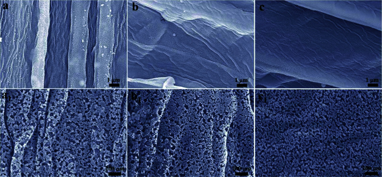
The SEM images of BN-SC and BN-SAC-n series are shown in Fig. S2 (ESI)† and 3. Obviously, the surface and inner cellular walls of BN-SC both show abundant uniformly distributed mesopores and a few macropores (Fig. S2, ESI†) which are probably produced during low-pressure rapid carbonization. Possible explanation for these pores is the rapid weight loss of sisal fiber and (NH4)2B4O7 in this stage isn't in consistent with the rate of fiber dimensional shrinkage and thus results in uniform pores on fiber surface and inner walls. After KOH activation, in spite of the etched micropores are too small to be observed on the fiber surface from the SEM images, the size and content of mesopores both increase (Fig. 3a1–c1) with the raise of (NH4)2B4O7 concentration, which is in good accordance with the TEM (Fig. S3, ESI†) and nitrogen adsorption–desorption results. The packing density of BN-SAC-n series is in the range of 0.43–0.53 g cm−3, comparable to common activated carbons (Table S1, ESI†).
Fig. 3. (a–c and a1–c1) SEM images of BN-SAC-n series, (a and a1) BN-SAC-3, (b and b1) BN-SAC-2 and (c and c1) BN-SAC-1.
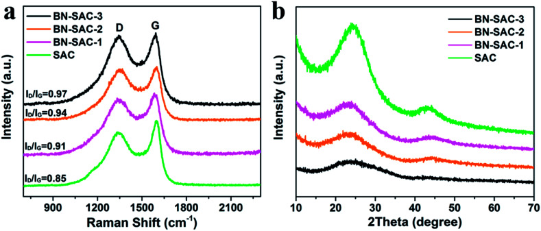
The Raman and XRD measurements were carried out to further study the structure of BN-SAC-n series, the corresponding results are shown in Fig. 4a and b, respectively. All samples exhibit two prominent peaks at around 1345 cm−1 assigned to D-bands representing the disordered carbon structure and 1600 cm−1 assigned to G-bands representing the tangential vibration of graphitic carbon.52,53 The integrated intensity ratio of ID/IG is 0.85 for SAC, 0.91 for BN-SAC-1, 0.94 for BN-SAC-2, and 0.97 for BN-SAC-3, suggesting that high level of B, N dual-doping would lead to disordered carbon structure with more defective graphitic crystallites.54Fig. 4b shows the XRD patterns of all samples. Two broad diffraction peaks at around 2θ = 24° and 44° appear on each curve, corresponding to (002) and (101) reflections of graphitic carbon, respectively.55 Compared with SAC, the BN-SAC-n series show broader peaks and lower peak intensity. As the B, N dual-doping level increases, the peak intensity continues reducing, indicating lower degree of graphitization which is in accordance with the results of Raman spectra.
Fig. 4. (a) Raman and (b) XRD spectra of SAC and BN-SAC-n series.
The X-ray photoelectron spectroscopy (XPS) measurements were carried out to investigate the surface chemical compositions and confirm the incorporation of B, N atoms. As shown in Fig. 5a, All XPS survey spectra exhibit similar shape with strong C and O signal as well as evident N and B signal. Specifically, the contents of C, O, B and N were estimated and listed in Table S2 (ESI).† As is shown, the content of B is 0.8, 2.4 and 3.8 at% and the content of N is 2.6, 4.0 and 4.5 at% for BN-SAC-1, BN-SAC-2 and BN-SAC-3, respectively. It is apparent high concentration of (NH4)2B4O7 aqueous solution increases the doping level of both B and N atoms. Moreover, the high-resolution spectra of B 1s and N 1s of BN-SAC-3 were fitted to investigate the detailed chemical compositions (Fig. 5b and c). It can be seen the B 1s spectrum was deconvolved into two peaks of N–B (192.2 eV) and B–CO2 (190.8 eV).56 The N 1s spectrum could be deconvolved into four peaks at 401.4, 400.5, 399.0 and 398.2 eV, corresponding to quaternary N, pyrrolic N, C–N–B and pyridinic N, respectively.57,58 In addition to N and B, the content of O also increases with the concentration of additive. These introduced functional groups including quaternary N, pyrrolic N, pyridinic N, C–O, O–C O and B–C functionalities have been proven to be effective in facilitating the electron transfer for higher electrical conductivity and providing a great deal of active sites for additional pseudocapacitance.31,34,35,56
Fig. 5. (a) XPS survey spectrum of BN-SAC-n series; (b and c) high-resolution B 1s and N 1s spectra of the BN-SAC-3.
3.2. Electrochemical performance of the BN-SAC-n
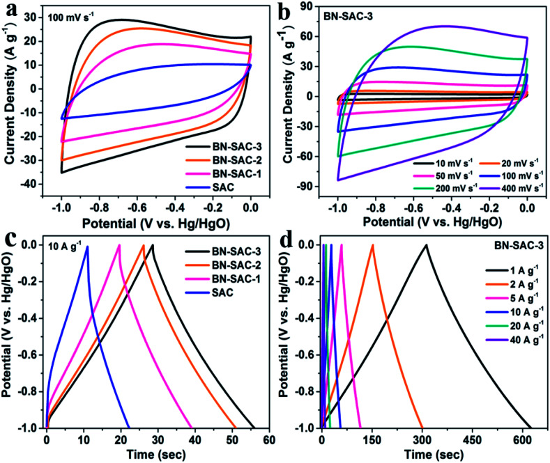
The electrochemical performance of BN-SAC-n series was first examined in a three-electrode system with 6 M KOH aqueous solution as electrolyte. Fig. 6a shows the cyclic voltammetry (CV) curves of BN-SAC-n series and SAC at a scan rate of 100 mV s−1, the BN-SAC-3 and BN-SAC-2 with higher mesoporosity (68.6 and 64.5%) and larger SSA (2017 and 1978 m2 g−1) both exhibit quasi-rectangular profiles with large loop area, indicating their superior electrical double-layer capacitive behavior at such a high scan rate. While for the BN-SAC-1 with relatively low mesoporosity (52.2%) and SSA (1802 m2 g−1), serious distortion and shrunken loop can be observed on its CV curve at the same scan rate. Besides, all BN-SAC-n series exhibit slight deviation curves at low potentials corresponding to pseudocapacitive behavior induced by the abundant B, N, O-containing functional groups.13 In contrast, the un-doped SAC with the lowest mesoporosity (36.6%) and SSA (1017 m2 g−1) prepared through conventional method shows a leaf-shape CV curve with the smallest loop area, indicating its poor capacitive performance.59 These results prove that higher doping level is beneficial for electrical double-layer capacitive behavior, especially at high scan rate. Notably, for the BN-SAC-3 with the highest doping level, it still shows quasi-rectangular CV curve with less distortion (Fig. 6b) even at an ultrahigh scan rate of 400 mV s−1, further demonstrating its excellent rate capability.
Fig. 6. (a) CV curves of SAC and BN-SAC-n series obtained at a scan rate of 100 mV s−1; (b) CV curves of the BN-SAC-3 obtained at scan rate ranging from 10–400 mV s−1; (c) galvanostatic charge–discharge curves of SAC and BN-SAC-n series measured at a current density of 10 A g−1; (d) galvanostatic charge–discharge curves of the BN-SAC-3 at current densities of 1–40 A g−1.
The galvanostatic charge–discharge profiles of all samples obtained at a current density of 10 A g−1 are shown in Fig. 6c. All BN-SAC-n series exhibit linear and symmetrical charge–discharge curves ascribed to ideal electrical double-layer capacitive behavior while obvious asymmetrical curve is observed for the SAC due to its dominant micropores with high diffusion resistance.60 As the doping level increases, the discharge time prolongs while the IR drop related to the equivalent series resistance (ESR) of the electrode reduces, resulting in significantly increased specific capacitance. Benefitting from its multiscale porous structure with the largest mesoporosity which reduces the inner resistance and facilitates ion diffusion inside the electrode, the BN-SAC-3 exhibits highly linear and symmetrical charge–discharge curve with gradually increasing IR drop from 1 A g−1 to 40 A g−1, as shown in Fig. 6d and S4.†
Fig. 7a shows the specific capacitance of all samples obtained from the discharge curves at different current densities. The BN-SAC-3 exhibits the highest specific capacitance of 304 F g−1 at a low current density of 1 A g−1 while the BN-SAC-2 and BN-SAC-1 respectively exhibits specific capacitance of 279 and 232 F g−1. As the current density increases from 1 A g−1 to 60 A g−1, the specific capacitance of all samples significantly decrease. However, the sample with higher doping level shows more flat curve with less capacitance loss at high current densities. At an ultrahigh current density of 60 A g−1, the BN-SAC-3 could still retain a high capacitance of 221 F g−1 (72.6% of that measured at 1 A g−1), indicating its best rate capability which is higher than those of biomass-derived porous carbon and heteroatomic doping carbon nanomaterials recently reported in the literatures (Table S3, ESI†). The BN-SAC-2 and BN-SAC-1 respectively shows capacitance of 162 and 73 F g−1 at the same current density due to lower SSA and mesoporosity. In contrast, the un-doped SAC exhibits a very low capacitance of 72 F g−1 at 20 A g−1 due to the high diffusion resistance induced by dominant micropores. These results from CV and galvanostatic charge–discharge profiles indicate that the BN-SAC-3 with the highest doping level exhibits best electrochemical behavior at high scan rate, owing to more functional groups which facilitate the electron transfer and contribute pseudocapacitance. Meanwhile, the multiscale porous structure with the largest mesoporosity and SSA highly promotes the ion diffusion and adsorption/desorption inside the electrodes. To further investigate the electrochemical performance of BN-SAC-n series, electrochemical impedance spectroscopy (EIS) were recorded at open circuit potential in the frequency range of 105 to 0.01 Hz. As shown in Fig. 7b, oblate semicircles reflecting the charge transfer resistance are observed in the high frequency region on all Nyquist plots while in the low frequency region nearly vertical lines corresponding to ideal electrical double-layer capacitive behavior appear on all profiles.14 As the doping level increases, the equivalent series resistance (ESR) obtained from the real axis intercept decreases, reaching the lowest value of 0.55 Ω for the BN-SAC-3. The change trend of charge transfer resistance obtained from the semicircle diameter is in accordance with the ESR, the measured value is respectively 0.46, 0.59, 0.65 and 1.83 Ω for BN-SAC-3, BN-SAC-2, BN-SAC-1 and SAC, proving that B, N dual-doping is beneficial for increasing the electrical conductivity. In addition, benefitting from their hierarchical macro–meso–microporous structure with abundant mesopores which facilitate the ion diffusion, the BN-SAC-n series show much higher slope in the low frequency region. Fig. 7c shows the cycling performance of BN-SAC-3 measured at a high current density of 10 A g−1 and a negligible capacitance loss (4.6%) is observed after 3000 cycles, indicative of its excellent cycling stability. Besides, no obvious electrochemical activation behavior appear during the initial stage of the profile, suggesting that the multiscale porous structure provides easy access for electrolyte ion diffusion while the abundant surface functional groups improve the wettability for quicker ion adsorption/desorption.59
Fig. 7. (a) Rate capability of SAC and BN-SAC-n series; (b) Nyquist plots of SAC and BN-SAC-n series; (c) cycling performance of BN-SAC-3 at a current density of 10 A g−1.
3.3. Electrochemical performance of the BN-SAC-3 in supercapacitors
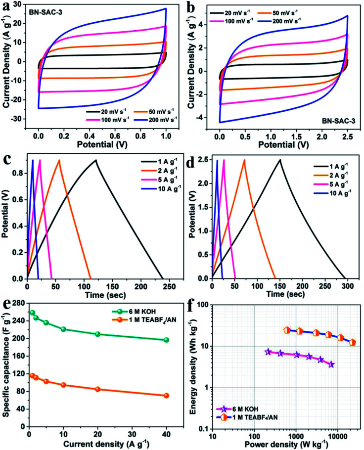
SSCs were assembled with the BN-SAC-3 as both positive and negative electrodes to rate its practical performance, the 6 M KOH and 1 M TEABF4/AN solution was respectively employed as the electrolyte. As shown in the Fig. S5,† for the SSC using 6 M KOH electrolyte, a stable voltage window could reach 0.9 V until obvious polarization behavior occur. While for the SSC using 1 M TEABF4/AN electrolyte, this value is significantly enhanced to 2.5 V, showing great potential in enhancing energy and power density of the supercapacitor. As shown in Fig. 8a and b, the supercapacitor exhibits quasi-rectangular shaped CV curves in a wide range of scan rate (20–200 mV s−1) using either electrolyte, indicative of its superior rate capability. Fig. 8c, d and S6† show the galvanostatic charge–discharge profiles of the device in the two different electrolytes. These curves remain linear and symmetrical characteristics in a wide range of 1–10 A g−1, further indicating the ideal electrical double-layer capacitive behavior of the as-assembled supercapacitors. Furthermore, the specific capacitance of the devices at various current densities were calculated from the charge–discharge curves, and the results are exhibited in Fig. 8e. At the current density of 1 A g−1, the supercapacitor shows a high specific capacitance of 258 F g−1 in aqueous electrolyte, while in the organic electrolyte it is only 116 F g−1 due to much larger electrolyte ions which cannot access into micropores and small mesopores. Nevertheless, the supercapacitor possesses superior rate capability in both aqueous and organic electrolytes, the specific capacitance could still retains 76.4% (197 F g−1) and 61.2% (71 F g−1) of the initial capacitance at the current density of 40 A g−1, respectively. The Ragone plots of the supercapacitor based on BN-SAC-3 is shown in Fig. 8f. Benefitting from the larger voltage window in 1 M TEABF4/AN electrolyte, the maximum energy density of the device can reach to 24.3 W h kg−1 at a power density of 612.8 W kg−1, which is much higher than that in 6 M KOH electrolyte (7.3 W h kg−1 at 215 W kg−1). Besides, the energy density could still retain as high as 12.3 W h kg−1 (3.6 W h kg−1 in aqueous electrolyte) when the power density reaches its maximum value of 22.45 kW kg−1 (6.9 kW kg−1 in aqueous electrolyte). In addition, the SSC using 6 M KOH and 1 M TEABF4/AN electrolyte respectively shows negligible capacitance loss of 5.2 and 3.8% after 3000 cycles (Fig. S7†), indicative of their excellent cycling stability.
Fig. 8. CV curves of BN-SAC-3 tested in (a) 6 M KOH and (b) 1 M TEABF4/AN electrolytes at scan rates of 20–200 mV s−1; galvanostatic charge–discharge curves of BN-SAC-3 tested in (c) 6 M KOH and (d) 1 M TEABF4/AN electrolytes at current densities of 1–10 A g−1; (e) rate capability of BN-SAC-3; (f) Ragone plots of BN-SAC-3-based symmetric supercapacitor with 6 M KOH and 1 M TEABF4/AN as electrolyte, respectively.
4. Conclusion
In conclusion, novel B, N dual-doped ACs with hierarchical macro–meso–microporous structure for high-rate EDLC electrodes were prepared from (NH4)2B4O7-containing sisal fibers through a facile strategy combining low-pressure rapid carbonization and KOH activation. As the concentration of B, N-containing reagent increases, the doping level of B and N, the SSA and the mesoporosity of the BN-SAC-n series all greatly increase, indicating the (NH4)2B4O7 effectively promotes the formation of mesopores and multiscale porous structure due to the rapid gas evaporation during its decomposition, in addition to endowing the BN-SAC with B, N dual-doping. Benefitting from the multiscale hierarchical structure built up by inherent cellular channels, mesopores on tracheid walls and etched micropores, the BN-SAC exhibit both high SSA and mesoporosity. Besides, the B, N dual-doping provides the BN-SAC with abundant functional groups for additional pseudocapacitance and improves their electrical conductivity and surface accessibility. With the highest SSA (2017 m2 g−1), mesoporosity (68.6%) and doping level of B, N atoms (3.8 and 4.5 at%, respectively), the BN-SAC-3 exhibits excellent electrochemical performance in both aqueous and organic electrolyte. For three-electrode test, the BN-SAC-3 shows a high specific capacitance of 304 F g−1 at 1 A g−1, which could still retain 72.6% when the current density increases to 60 A g−1. After assembling into SSCs, the BN-SAC-3 shows a maximum specific capacitance of 258 F g−1 at 1 A g−1 in aqueous electrolyte (116 F g−1 in organic electrolyte) with a high retention of 76.4% at 40 A g−1 (61.2% in organic electrolyte), and delivers a maximum energy density of 24.3 W h kg−1 at a power density of 612.8 W kg−1 in organic electrolyte. This work provides an effective and economic method for the synthesis of hierarchical macro–meso–microporous ACs for high-performance EDLC electrodes and is expected to be applied on other biomasses on a large scale.
Conflicts of interest
There are no conflicts to declare.
Supplementary Material
Acknowledgments
This work was financially supported by the National Key R&D Program of China (No. 2017YFB1103500), the National Natural Science Foundation of China (No. 51302220, 51672218 and 51632007) and the Ministry of Business, Innovation and Employment Endeavour Fund of New Zealand (No. 3000033429).
Electronic supplementary information (ESI) available. See DOI: 10.1039/c8ra09663e
References
- Yang Z. Tian J. Yin Z. Cui C. Qian W. Wei F. Carbon. 2018;141:467–480. doi: 10.1016/j.carbon.2018.10.010. [DOI] [Google Scholar]
- Wu H. Zhang Y. Cheng L. Zheng L. Li Y. Yuan W. Yuan X. Energy Storage Materials. 2016;5:8–32. doi: 10.1016/j.ensm.2016.05.003. [DOI] [Google Scholar]
- Zhang J. Jin L. Cheng J. Hu H. Carbon. 2013;55:221–232. doi: 10.1016/j.carbon.2012.12.030. [DOI] [Google Scholar]
- He X. Li R. Qiu J. Xie K. Ling P. Yu M. Zhang X. Zheng M. Carbon. 2012;50:4911–4921. doi: 10.1016/j.carbon.2012.06.020. [DOI] [Google Scholar]
- Huang F. Chen D. Energy Environ. Sci. 2012;5:5833–5841. doi: 10.1039/C1EE01989A. [DOI] [Google Scholar]
- Sun P. Deng Z. Yang P. Yu X. Chen Y. Liang Z. Meng H. Xie W. Tan S. Mai W. J. Mater. Chem. A. 2015;3:12076–12080. doi: 10.1039/C5TA02316E. [DOI] [Google Scholar]
- Wu Z. Yang S. Zhang L. Wagner J. B. Feng X. Müllen K. Energy Storage Materials. 2015;1:119–126. doi: 10.1016/j.ensm.2015.09.004. [DOI] [Google Scholar]
- Wang L. J. El-Kady M. F. Dubin S. Hwang J. Y. Shao Y. Marsh K. McVerry B. Kowal M. D. Mousavi M. F. Kaner R. B. Adv. Energy Mater. 2015;5:1500786. doi: 10.1002/aenm.201500786. [DOI] [Google Scholar]
- Wang G. Zhang L. Zhang J. Chem. Soc. Rev. 2012;41:797–828. doi: 10.1039/C1CS15060J. [DOI] [PubMed] [Google Scholar]
- Zhang L. Zhang F. Yang X. Leng K. Huang Y. Chen Y. Small. 2013;9:1342–1347. doi: 10.1002/smll.201202943. [DOI] [PubMed] [Google Scholar]
- Wu H. Zhang Y. Yuan W. Zhao Y. Luo S. Yuan X. Zheng L. Cheng L. J. Mater. Chem. A. 2018;6:16617–16626. doi: 10.1039/C8TA05673K. [DOI] [Google Scholar]
- Zhai Y. Dou Y. Zhao D. Fulvio P. F. Mayes R. T. Dai S. Adv. Mater. 2011;23:4828–4850. doi: 10.1002/adma.201100984. [DOI] [PubMed] [Google Scholar]
- Jin Z. Yan X. Yu Y. Zhao G. J. Mater. Chem. A. 2014;2:11706–11715. doi: 10.1039/C4TA01413H. [DOI] [Google Scholar]
- Wu H. Cheng L. Zhang Y. Yuan W. Zheng L. Carbon. 2017;116:518–527. doi: 10.1016/j.carbon.2017.02.029. [DOI] [Google Scholar]
- Cao Y. Wang K. Wang X. Gu Z. Fan Q. Gibbons W. Hoefelmeyer J. D. Kharel P. R. Shrestha M. Electrochim. Acta. 2016;212:839–847. doi: 10.1016/j.electacta.2016.07.069. [DOI] [Google Scholar]
- Sevilla M. Fuertes A. B. ChemSusChem. 2016;9:1880–1888. doi: 10.1002/cssc.201600426. [DOI] [PubMed] [Google Scholar]
- Fan X. Yu C. Yang J. Ling Z. Hu C. Zhang M. Qiu J. Adv. Energy Mater. 2015;5:1401761. doi: 10.1002/aenm.201401761. [DOI] [Google Scholar]
- Shan D. Yang J. Liu W. Yan J. Fan Z. J. Mater. Chem. A. 2016;4:13589–13602. doi: 10.1039/C6TA05406D. [DOI] [Google Scholar]
- Wang H. Xu Z. Kohandehghan A. Li Z. Cui K. Tan X. Stephenson T. J. King'ondu C. K. Holt C. M. Olsen B. C. ACS Nano. 2013;7:5131–5141. doi: 10.1021/nn400731g. [DOI] [PubMed] [Google Scholar]
- Péan C. Merlet C. Rotenberg B. Madden P. A. Taberna P.-L. Daffos B. Salanne M. Simon P. ACS Nano. 2014;8:1576–1583. doi: 10.1021/nn4058243. [DOI] [PubMed] [Google Scholar]
- Forse A. C. Griffin J. M. Merlet C. Carretero-Gonzalez J. Raji A.-R. O. Trease N. M. Grey C. P. Nat. Energy. 2017;2:16216. doi: 10.1038/nenergy.2016.216. [DOI] [Google Scholar]
- Zhang F. Liu T. Li M. Yu M. Luo Y. Tong Y. Li Y. Nano Lett. 2017;17:3097–3104. doi: 10.1021/acs.nanolett.7b00533. [DOI] [PubMed] [Google Scholar]
- Ervin M. H. Nanotechnology. 2015;26:234003. doi: 10.1088/0957-4484/26/23/234003. [DOI] [PubMed] [Google Scholar]
- Zhao Q. Wang X. Liu J. Wang H. Zhang Y. Gao J. Lu Q. Zhou H. Electrochim. Acta. 2015;154:110–118. doi: 10.1016/j.electacta.2014.12.052. [DOI] [Google Scholar]
- Yuan W. Cheng L. Zhang Y. Li Y. Guo X. Wu H. Zheng L. Ceram. Int. 2017;43:11563–11568. doi: 10.1016/j.ceramint.2017.05.087. [DOI] [Google Scholar]
- Yuan W. Zhang Y. Cheng L. Wu H. Zheng L. Zhao D. J. Mater. Chem. A. 2016;4:8932–8951. doi: 10.1039/C6TA01546H. [DOI] [Google Scholar]
- Jiang H. Cai X. Qian Y. Zhang C. Zhou L. Liu W. Li B. Lai L. Huang W. J. Mater. Chem. A. 2017;5:23727–23736. doi: 10.1039/C7TA07727K. [DOI] [Google Scholar]
- Senokos E. Reguero V. Cabana L. Palma J. Marcilla R. Vilatela J. J. Adv. Mater. Technol. 2017;2:1600290. doi: 10.1002/admt.201600290. [DOI] [Google Scholar]
- Peng H., Li Q. and Chen T., Industrial applications of carbon nanotubes, William Andrew, 2016 [Google Scholar]
- Simon P. Gogotsi Y. Acc. Chem. Res. 2012;46:1094–1103. doi: 10.1021/ar200306b. [DOI] [PubMed] [Google Scholar]
- Jeong H. M. Lee J. W. Shin W. H. Choi Y. J. Shin H. J. Kang J. K. Choi J. W. Nano Lett. 2011;11:2472–2477. doi: 10.1021/nl2009058. [DOI] [PubMed] [Google Scholar]
- Chen Y. Zhang X. Zhang D. Yu P. Ma Y. Carbon. 2011;49:573–580. doi: 10.1016/j.carbon.2010.09.060. [DOI] [Google Scholar]
- Rui X. Yan Q. Skyllas-Kazacos M. Lim T. M. J. Power Sources. 2014;258:19–38. doi: 10.1016/j.jpowsour.2014.01.126. [DOI] [Google Scholar]
- Hou J. Cao C. Idrees F. Ma X. ACS Nano. 2015;9:2556–2564. doi: 10.1021/nn506394r. [DOI] [PubMed] [Google Scholar]
- Wang C. Guo Z. Shen W. Xu Q. Liu H. Wang Y. Adv. Funct. Mater. 2014;24:5511–5521. doi: 10.1002/adfm.201401006. [DOI] [Google Scholar]
- Zheng Y. Jiao Y. Ge L. Jaroniec M. Qiao S. Z. Angew. Chem. 2013;125:3192–3198. doi: 10.1002/ange.201209548. [DOI] [PubMed] [Google Scholar]
- Paraknowitsch J. P. Thomas A. Energy Environ. Sci. 2013;6:2839–2855. doi: 10.1039/C3EE41444B. [DOI] [Google Scholar]
- Hu Z. Li S. Cheng P. Yu W. Li R. Shao X. Lin W. Yuan D. J. Mater. Sci. 2016;51:2627–2633. doi: 10.1007/s10853-015-9576-x. [DOI] [Google Scholar]
- Qu K. Zheng Y. Jiao Y. Zhang X. Dai S. Qiao S. Z. Adv. Energy Mater. 2017;7:1602068. doi: 10.1002/aenm.201602068. [DOI] [Google Scholar]
- Wang M. Yang Y. Yang Z. Gu L. Chen Q. Yu Y. Adv. Sci. 2017;4:1600468. doi: 10.1002/advs.201600468. [DOI] [PMC free article] [PubMed] [Google Scholar]
- Xia Q. Yang H. Wang M. Yang M. Guo Q. Wan L. Xia H. Yu Y. Adv. Energy Mater. 2017;7:1701336. doi: 10.1002/aenm.201701336. [DOI] [Google Scholar]
- Liu X. Antonietti M. Adv. Mater. 2013;25:6284–6290. doi: 10.1002/adma.201302034. [DOI] [PubMed] [Google Scholar]
- Hao G. P. Lu A. H. Dong W. Jin Z. Y. Zhang X. Q. Zhang J. T. Li W. C. Adv. Energy Mater. 2013;3:1421–1427. doi: 10.1002/aenm.201300383. [DOI] [Google Scholar]
- Falco C. Sieben J. M. Brun N. Sevilla M. Van der Mauelen T. Morallon E. Cazorla-Amoros D. Titirici M. M. ChemSusChem. 2013;6:374–382. doi: 10.1002/cssc.201200817. [DOI] [PubMed] [Google Scholar]
- Sun L. Tian C. Fu Y. Yang Y. Yin J. Wang L. Fu H. Chem.–Eur. J. 2014;20:564–574. doi: 10.1002/chem.201303345. [DOI] [PubMed] [Google Scholar]
- Fang Y. Lv Y. Che R. Wu H. Zhang X. Gu D. Zheng G. Zhao D. J. Am. Chem. Soc. 2013;135:1524–1530. doi: 10.1021/ja310849c. [DOI] [PubMed] [Google Scholar]
- Wang L. Mu G. Tian C. Sun L. Zhou W. Yu P. Yin J. Fu H. ChemSusChem. 2013;6:880–889. doi: 10.1002/cssc.201200990. [DOI] [PubMed] [Google Scholar]
- Dizbay-Onat M. Vaidya U. K. Lungu C. T. Ind. Crops Prod. 2017;95:583–590. doi: 10.1016/j.indcrop.2016.11.016. [DOI] [Google Scholar]
- Arthanarieswaran V. Kumaravel A. Kathirselvam M. Mater. Des. 2014;64:194–202. doi: 10.1016/j.matdes.2014.07.058. [DOI] [Google Scholar]
- Dizbay-Onat M. Floyd E. Vaidya U. K. Lungu C. T. Fibers Polym. 2018;19:805–811. doi: 10.1007/s12221-018-7866-z. [DOI] [Google Scholar]
- Li B. Energy Environ. Sci. 2016;9:102–106. doi: 10.1039/C5EE03149D. [DOI] [Google Scholar]
- Yang J. Zhou X. Wu D. Zhao X. Zhou Z. Adv. Mater. 2017;29:1604108. doi: 10.1002/adma.201604108. [DOI] [PubMed] [Google Scholar]
- Wang Y. Wang C. Guo H. Wang Y. Huang Z. RSC Adv. 2017;7:1588–1592. doi: 10.1039/C6RA27088C. [DOI] [Google Scholar]
- Zhang L. Xia G. Guo Z. Li X. Sun D. Yu X. Int. J. Hydrogen Energy. 2016;41:14252–14260. doi: 10.1016/j.ijhydene.2016.06.016. [DOI] [Google Scholar]
- Biswal M. Banerjee A. Deo M. Ogale S. Energy Environ. Sci. 2013;6:1249–1259. doi: 10.1039/C3EE22325F. [DOI] [Google Scholar]
- Ling Z. Wang Z. Zhang M. Yu C. Wang G. Dong Y. Liu S. Wang Y. Qiu J. Adv. Funct. Mater. 2016;26:111–119. doi: 10.1002/adfm.201504004. [DOI] [Google Scholar]
- Wu Z. S. Winter A. Chen L. Sun Y. Turchanin A. Feng X. Müllen K. Adv. Mater. 2012;24:5130–5135. doi: 10.1002/adma.201201948. [DOI] [PubMed] [Google Scholar]
- Wang M. Yang Z. Li W. Gu L. Yu Y. Small. 2016;12:2559–2566. doi: 10.1002/smll.201600101. [DOI] [PubMed] [Google Scholar]
- Li Z. Zhang L. Amirkhiz B. S. Tan X. Xu Z. Wang H. Olsen B. C. Holt C. M. B. Mitlin D. Adv. Energy Mater. 2012;2:431–437. doi: 10.1002/aenm.201100548. [DOI] [Google Scholar]
- Raymundo-Piñero E. Cadek M. Béguin F. Adv. Funct. Mater. 2009;19:1032–1039. doi: 10.1002/adfm.200801057. [DOI] [Google Scholar]
Associated Data
This section collects any data citations, data availability statements, or supplementary materials included in this article.


