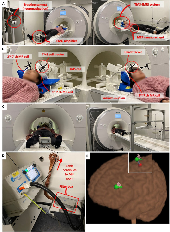
Figure 1.
Example of TMS-fMRI set up. (A) This particular example of TMS-fMRI set up includes MR compatible TMS coils (Magventure, Farum, Denmark), MR coils (16), neuronavigation system (Localite, Bonn, Germany), and a BrainAmp ExG MR amplifier (BrainProducts, Gilching, Germany) for electromyographic (EMG) measurements to determine motor threshold (MT). (B) TMS coil is mounted on a holder which goes in the bore of the scanner. The holder system is attached to the scanner bed so that it moves together. The MR head coil, in this example, is two thin and flat seven channel coils. One is attached below the TMS coil, and the other is stabilized on the other side of the head using a vacuum pillow. Two trackers on the forehead and coil enable neuronavigation. (C) EMG amplifier continues to record the motor evoked potential (MEP) and the neuronavigation system tracks the TMS coil location throughout the scanning session. (D) TMS device remains in the technical room as it is ferromagnetic. The TMS coil is connected to the MRI room by a 6-m cable through a hole in the wall. The cable is covered with a filter tube, and a filter box is installed along the cable. (E) Neuronavigation system shows the location of the stimulation. The red dot is calculated with a coordinate that defines the target point. By defining the coil orientation, it calculates the entering point which is the green dot with the green bar showing the coil handle orientation. The pink pins show the actual stimulation location, which is recorded each time a TMS pulse is applied during the TMS-fMRI session. These pink pins can be recorded during the concurrent TMS-fMRI session and can be used for the post-analysis as far as the head and coil trackers are visible in the MR bore as shown in panel (C).

