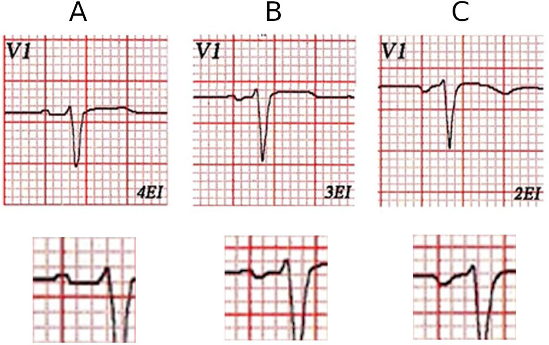
Figure 4:

(A) This is V1 lead of a healthy patient with normal left atrial size by echocardiography. V1 electrode placed in normal location (4th ICS) (A), 3rd ICS (B), and in 2nd ICS (C). It is clear that the normal P wave in the 4th ICS becomes progressively more negative (B and C) as the electrode of V1 is placed in higher ICS.
ICS, intercostal space
