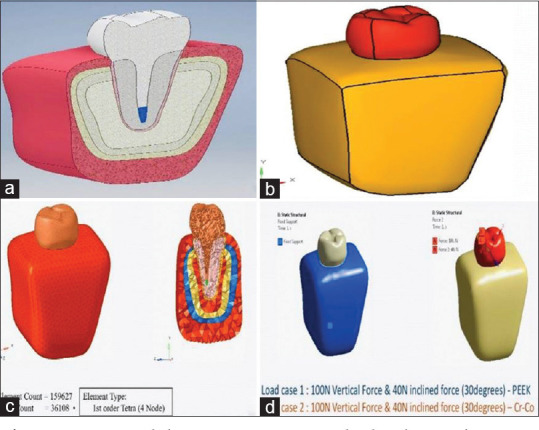
Figure 1.

Model preparation and load application. (a) Axisymmetric model representing the various parts in cross section. (b) The final element model geometry obtained on the computer screen by the provision of various entities such as grids, lines, and patches. (c) The mesh of the tooth model was created by segmenting the entire tooth structure into small cubical forms to analyze the stress caused in each cube. (d) A static load of a 100N and 40N were simultaneously applied on the second premolar tooth in a vertical and oblique direction (30° angulations), respectively for both the materials (i.e., polyether ether ketone and Metal)
