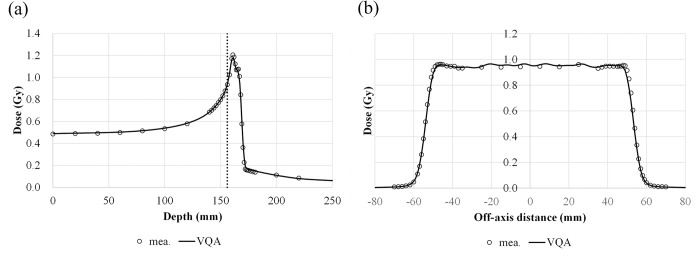
Fig 8. Comparison of the TPS-calculated and measured dose profiles for a field size of 100 × 100 mm2 with a 6-mm SOBP.
(a) The depth–dose profile along the central axis; the vertical dashed line represents the position of the measured lateral profile. (b) The lateral-dose profile at 156-mm depth; the circles and solid lines are the measured and calculated profiles, respectively.

