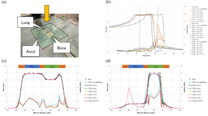
Fig 9. Results of the scanned-beam model compared with measurements in heterogeneous media.
(a) The heterogeneous phantom and measurement setup; the yellow arrow represents the incident beam’s direction. (b) The depth–dose profile penetrating each material; the circle, triangle, and square represent measurements in the acrylic, bone, and lung materials, respectively. The orange, blue, and green solid lines are the calculated profiles in acrylic, bone, and lung materials, respectively. The color in the legend of calculations changes according to the number of beam splittings. The vertical black dashed lines represent the measured lateral profile positions. (c and d) Lateral-dose profiles at 66 and 105 mm, respectively; the circles represent the measured profile, whereas the sky blue, blue, green, light yellow, yellow, orange, and pink solid lines are the calculated profiles with no splitting and with beam splittings 3 × 3 (default), 4 × 4, 5 × 5, 7 × 7, 9 × 9, and 15 × 15, respectively. The right vertical axis indicates the gamma value of 1D local-gamma-index analysis at a distance-to-agreement of 2 mm and a dose difference of 2%, with a 10% threshold.

