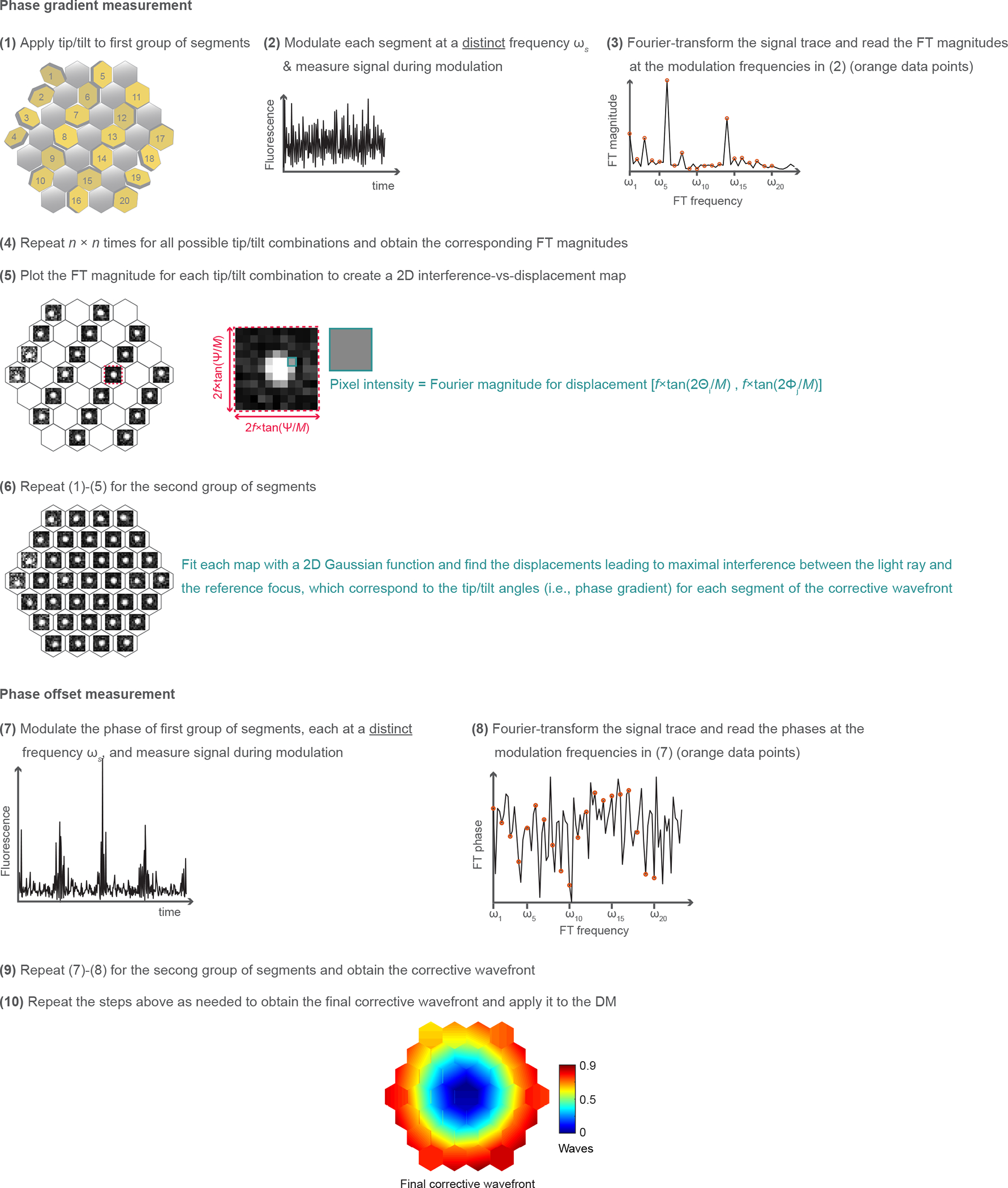
Extended Data Fig. 1 |. Schematics of the aberration measurement method.

(1) We fix the tip, tilt, and piston of one group of 17 segments, and add to the remaining 20 pupil segments a specific tip angle Θi and tilt angle Φj (i, j = 1,2,…n) chosen randomly from an array of n angles spaced between −Ψ/2 and Ψ/2. (2) We modulate the phase or intensity of all 20 beamlets, at a distinct frequency ωs (s = 1,2,…20), and record the fluorescence signal. (3) We Fourier transform (FT) the recorded signal trace and measure the Fourier magnitudes at each ωs. (4) This procedure is repeated n × n times for all tip and tilt angles. (5) For each beamlet, we plot the Fourier magnitudes versus the displacements (Xi, Yj) and construct a 2D map of interference strength of this beamlet with the reference focus at different focal displacements. Here, Xi = f*tan(2Θi/M) and Yj = f*tan(2Φj/M); f: focal length of the objective; M: magnification from the DM to objective back focal plane. (6) We repeat steps (1)-(5), with the group of 20 pupil segments fixed, while modulating the remaining 17 segments. We fit each map with a 2D Gaussian function and find the displacements leading to maximal interference between the light ray and the reference focus, corresponding to the tip and tilt angles for each segment of the corrective wavefront. (7) We modulate the phases of the first 20 rays by piston-displacing each corresponding mirror segment at a distinct frequency ωs while keeping the phases of the remaining rays constant. The resulting fluorescence trace is recorded. (8) We FT the recorded fluorescence trace and read out the phase offsets that would lead to constructive interference with the reference focus at the modulation frequencies ωs. (9) We modulate the phases of the remaining 17 segments while keeping the phases of the first 20 segments unchanged and obtain the corrective wavefront. (10) We repeat the steps above as needed to obtain the final corrective wavefront and apply it to the DM. See detailed description in Methods.
